5 - 5
5.1 Q Series Safety Relay Module
5.1.3 Part names and settings
5
SETTINGS AND PROCEDURES BEFORE
OPERATION
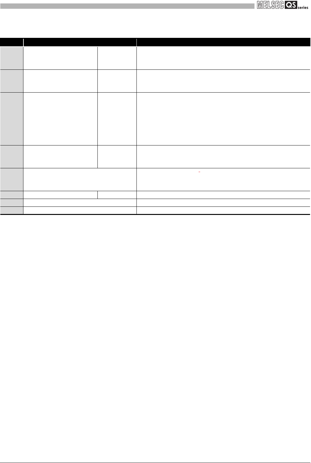
Table 5.1 Part names (2/2)
Number Name
Description
2)
Module power supply part
terminal block
POWER
+ 24V: Module power supply + 24V terminal
24G: Module power supply 24G terminal
FG: Module power supply FG terminal
3)
Extension communication part
terminal block
LOCAL COM
EA, EB, EG: Data terminal for extension communication
SLD: Shielding wire terminal
EP: Power supply terminal for extension module
4)
Safety power supply, safety
input part terminal block
S INPUT
+ 24V: Safety part power supply + 24V terminal
24G: Safety part power supply 24G terminal
XS0, XS1: Start-up/off check terminal
X0: Safety input X0 input terminal
COM0: Safety input X0 COM terminal
X1: Safety input X1 input terminal
COM1: Safety input X1 COM terminal
5)
Safety output part terminal
block
S OUTPUT
Z00, Z01: Safety relay output terminal
Z10, Z11: Safety relay output terminal
Z20, Z21: Safety relay output terminal
6) Start-up mode setting switch
A switch for setting start-up
mode
"A" side: Auto mode
"M" side: Manual mode
7) Safety part extension connector OUT A connector for connecting an extension module
8) Module fixing hook A hook for fixing a module to a base unit (One-touch installation)
9) Module mounting lever A lever for mounting a module on a base unit


