Positioning Control Actual Positioning 5
5-4
5.2.2 Writing the program
Using FX-PCS-VPS\Win-E, re-create the flow chart program shown in section 5.2.1.
If assistance is required in the operation of the software, please refer to the Software manual
JY992D86801.
When opening a new file in VPS, choose ‘FX(2N)/E-20GM with simultaneous 2 axis’
The example program is designed to utilize the real time monitor function of VPS software. If a
mechanical plotter is being used substitute the ‘DRV Ret’ command for a ‘DRVZ’, return to
origin command. Be sure to set up the plotter in accordance with the instructions and
guidelines applicable to and supplied with your specific plotter.
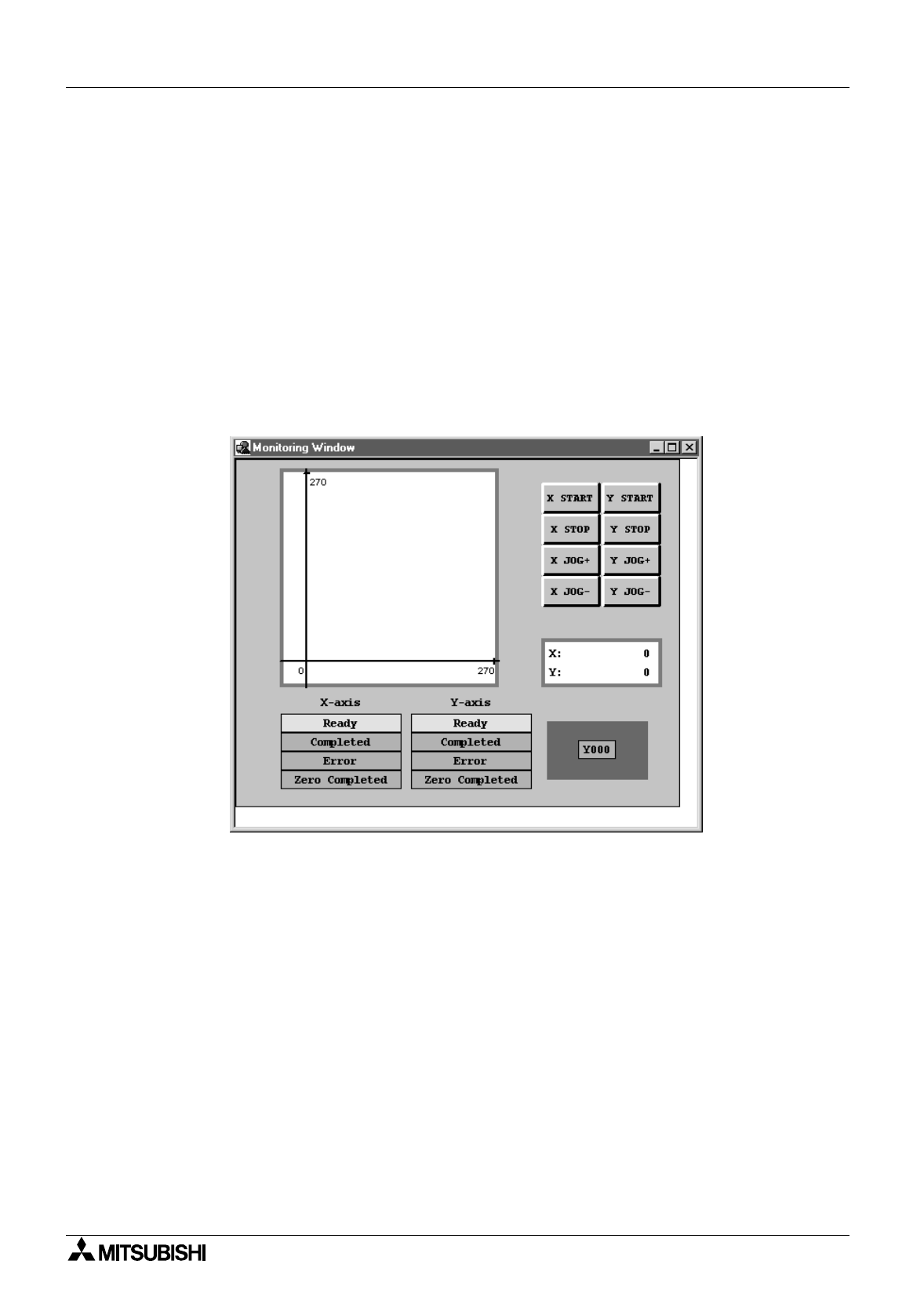
Along with the Flow chart, create a monitoring window similar to the one shown below.
All of the items on the monitoring window can be found under the insert tab on the main menu
at the top of the screen.
Items inserted include:
Current Position
Plotting (double click on plot area to change the scale)
Device Status (Y0)
Manual Operation (Start, Stop, Jog -, Jog +, for both X and Y axes, each inserted separately)
FX-GM Status
Plus, a rectangle from the drawing tool bar, to highlight the Y0 indicator.


