P 6/17
[3] DISASSEMBLY/ASSEMBLY
[3] -2. Barrel, Tool Holder, Cylinder Section
Repair
ASSEMBLY
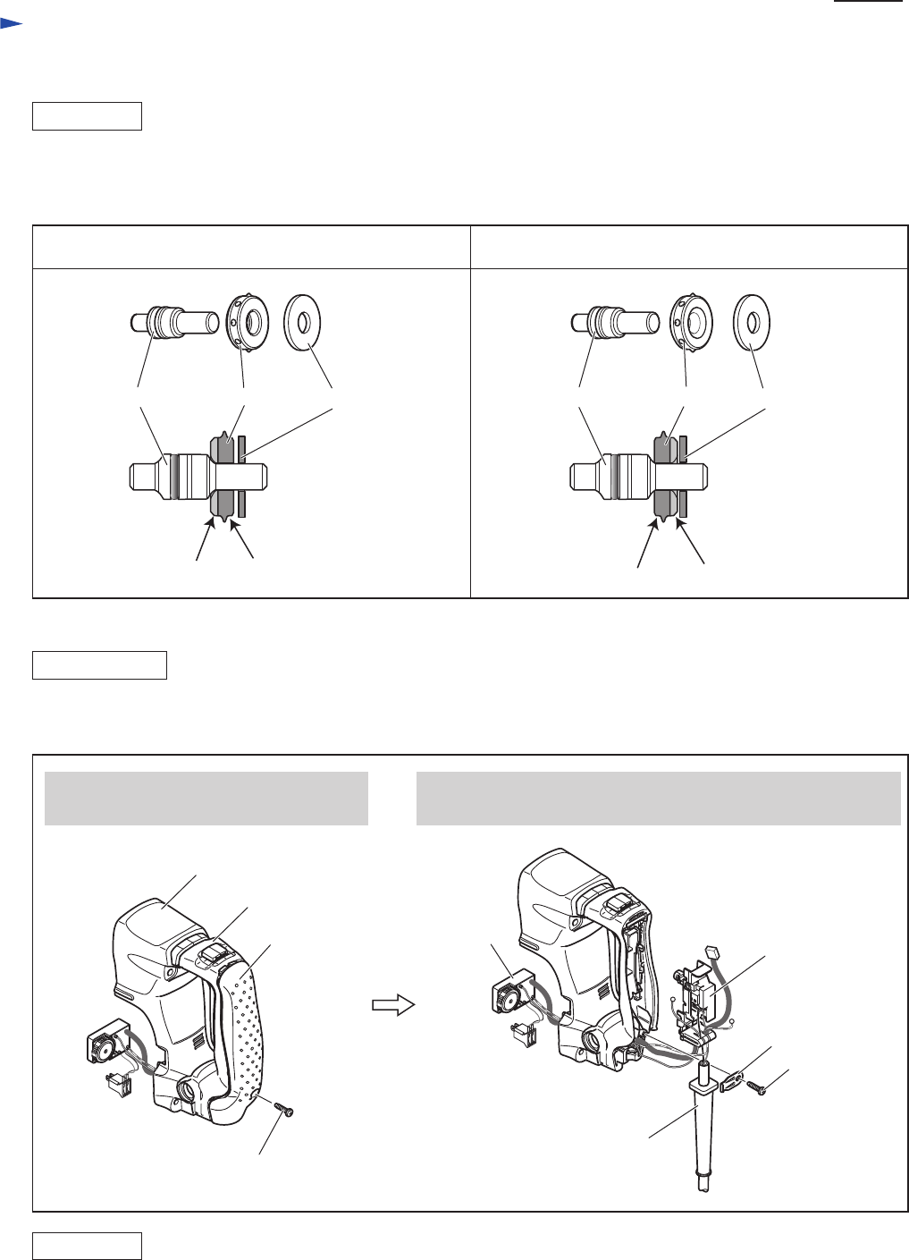
Fig. 9
Do the reverse of the disassembling steps.
Note: Rubber ring 13 is directional when assembled to Impact bolt.
Be sure to assemble as illustrated to left in Fig. 9.
ASSEMBLY
Do the reverse of the disassembling steps.
DISASSEMBLY
[3] -3. Electrical Parts in Handle Section
Correct Wrong
Rubber ring 13
Impact bolt Flat washer 12
Rubber portion
Metal portion
Rubber portion
Metal portion
Rubber ring 13
Impact bolt Flat washer 12
1) Disassemble Handle section as described in Fig. 2
2) The electrical Parts can be replaced as described in Fig. 10.
1. Disassemble Handle cover from Handle
by unscrewing 4x18 tapping screw.
2. Disconnect all the Lead wires from Switch.
Controller, Switch and Power supply cord can now be replaced.
Fig. 10
Handle cover
Handle base
4x18 Tapping screw (1 pc)
Handle
Controller
Switch
4x18 Tapping
screw (1 pc)
Power supply cord
Strain relief


