


P 10/17
[3] DISASSEMBLY/ASSEMBLY
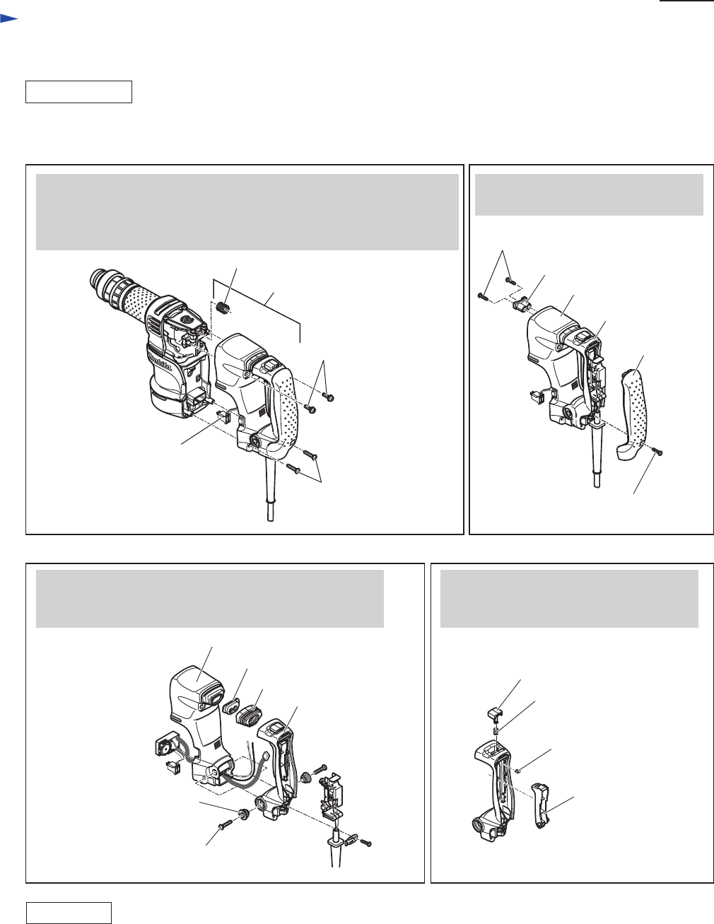
[3] -6. Handle Section
Repair
DISASSEMBLY
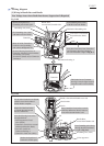
M5x20 Pan head
screw (2 pcs)
5x25 Tapping
screw (2 pcs)
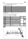
Handle section
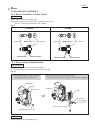
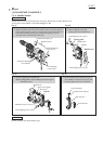
Handle section consists of the following main parts: Handle base, Handle, Handle cover
And it can be disassembled as illustrated in Figs. 17 - 20.
Handle base
Handle
Lock-on button
Stop ring E-4
Switch Lever
Compression spring 8
Dust cover
Dust cover support
Spring guide
Handle cover
Handle base
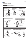
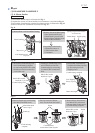
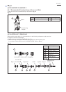
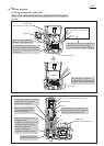
3. Separate Handle from Handle base.
Note: See Fig. 10 for disassembling the electrical parts
in Handle section.
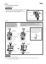
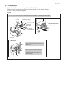
4. Remove Switch lever and Stop ring E-4
from Handle. Compression spring 8 and
Lock-on button can now be removed.
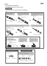
Handle
Shoulder sleeve 6 (2 pcs)
Fig. 17 Fig. 18
Fig. 19 Fig. 20
4x18 Tapping screw (2 pcs)
4x18 Tapping screw (1 pc)
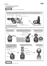
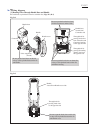
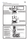
1. Separate Handle section from the machine first by removing the four
screws illustrated below, then by disconnecting Connector housing of
Controller from Motor housing; Compression spring 14 can be
removed from Crank housing in this step.
2. Remove Handle cover and
Spring guide from Handle base.
Connector housing
of Controller
Compression spring 14
5x25 Tapping screw (2 pcs)
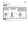
ASSEMBLY
Do the reverse of the disassembling steps.