


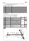
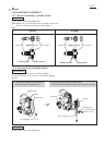
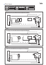

Wiring diagram
P 13/17
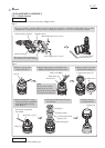
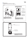
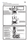
Handle base,
viewed from
Controller side
Handle
Through hole for
passing Lead wires
from Controller and
Connector housing
to the opposite side
Handle cover
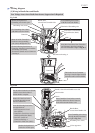
Handle,
viewed from Handle cover side
Handle base
Controller
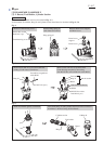
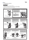
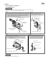
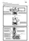
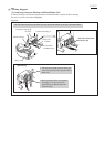
Be careful not to pinch the Lead wires with the ribs. (Figs. D-2, D-3)
[1] Routing Wires Through Handle Base and Handle
Fig. D-2
Fig. D-3
Do not put the Lead wires on this rib
or they will be pinched between the rib
and Handle.
Do not to put the Lead wires on these ribs
or they will be pinched between the ribs
and Motor housing.
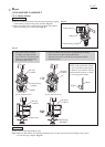
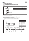
Through hole for
passing Grounding
(Earth) wire from
the opposite side
Through hole for
passing Lead wires
to the opposite side
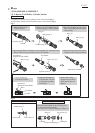
Do not to put the Lead wires on this rib
or they will be pinched between the rib
and Handle cover.
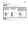
Noise suppressor
(if used)
Do not to put the Lead wire (clear)
of Noise suppressor on these ribs.