


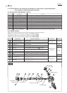
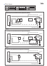
Wiring diagram
P 14/17
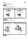
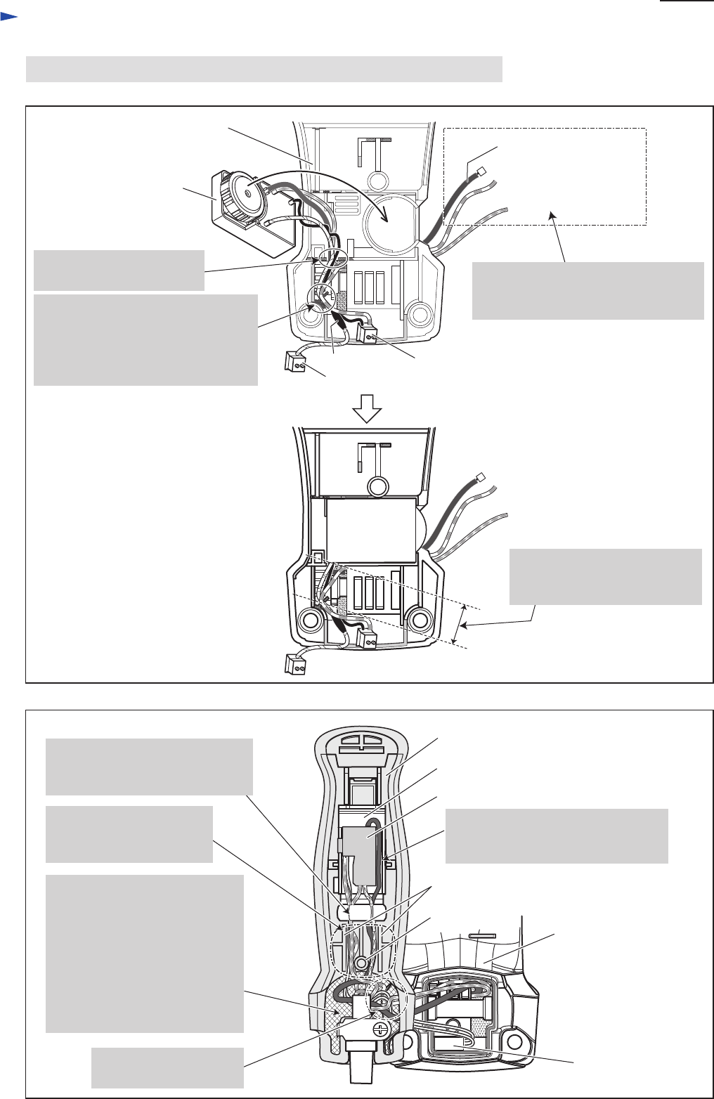
Fig. D-4A
Fig. D-5A
Handle base,
viewed from Controller side
Handle base,
viewed from Handle side
Handle, viewed from Handle cover side
red
blue
Lead wires covered with
Polyolefin tube (black)
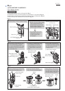
Controller
Connector housing A
Connector housing B
Choke coil
Controller
Noise suppressor
Switch
Switch holder
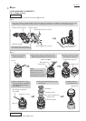
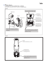
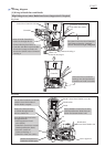
Pass the following Lead wires
through this hole:
*Noise suppressor's Lead
wires (black)
*Controller’s Lead wires covered
with Polyolefin tube (black)
*Lead wire (red) from
Connector housing A
*Controller's Lead wire (white)
Pass Controller’s Lead wires covered
with Polyolefin tube (black) between
Switch and Switch holder's wall.
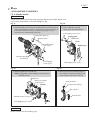
[2] Wiring in Handle Base and Handle
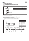
High Voltage Areas where Radio Interference Suppression Is Required
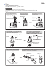
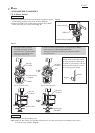
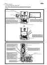
boss
rib
Put the slack portion of
Lead wires in this space.
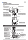
Route all of the Controller's
Lead wires through this slit.
Fix the following Lead wires of
Controller with this Lead wire holder:
*Lead wire (orange) to Choke coil
*Lead wires (black, red) to Connector
housing A
Pass these Lead wires from Controller
and Connector housing A through
the hole illustrated to right in Fig. D-2.
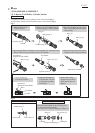
The Lead wires to Connector
housings must be tight between
Controller and Lead wire holder.
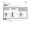
Route all of the Lead wires
to Switch through between
the boss and the rib.
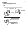
Fix all of the Lead wires to Switch
with this Lead wire holder of
Switch holder complete.