


19
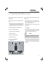
7. Assembly
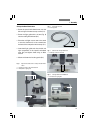
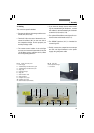
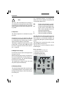
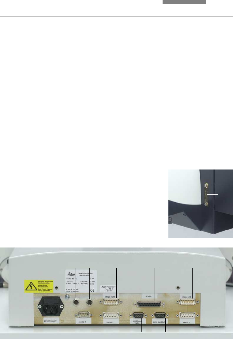
7.5 Cabling
The connector panel is labeled.
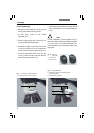
• Connect the left and right stage cables to ter-
minals (17.4) and (17.6).
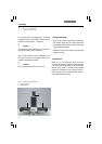
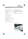
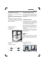
• Terminal (17.5) on the rear of the stand is con-
nected to terminal (18.1) on the rear side of
the comparison bridge. For this purpose, use
the 25-pin bridge cable.
• The remote control cables of the cold light
sources are connected to terminals (17.9) and
(17.10). When using a cold light source, select
the corresponding terminal.
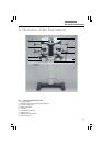
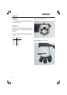
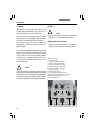
Fig. 17 Stand connector panel
1 Power supply
2 Transmitted light condenser lens, right
3 Transmitted light condenser lens, left
4 Stage, right
5 Comparison bridge
6 Stage, left
7 Serial interface 1 (PC)
8 Serial interface 2
9 Cold light source, right
10 Cold light source, left
11 Serial interface 3 (Smart Move)
Fig. 18 Rear side
of the comparison bridge
1 Connection
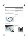
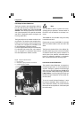
• If you have not already done so when install-
ing the transmitted light illuminator, connect
the cables for the transmitted light condenser
to terminal (17.2) and/or (17.3).
• The optional Smart Move control panel is con-
nected to the serial interface 3 (17.11).
• The RS232C interface (17.7) is intended for
connecting a PC.
• Finally, connect the comparison macroscope
and the cold light illuminator to the power
supply using the power cable.
1
123 4 5 6
7891011