


6
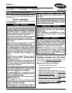
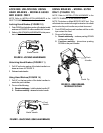
FIGURE 13 - TRANSPORT FEATURE -
MODEL 65900 ONLY
Brake
Seat
Transport Handle
Footrests
Brake
Footrest
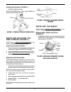
MODELS 65900,65800 AND 65700
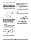
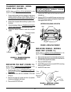
REPLACING THE SEAT (FIGURE 14)
NOTE: Refer to INSTALLATION WARNINGS in the
SAFETY SUMMARY in this instruction sheet.
1. Open the rollator. Refer to
OPENING/FOLDING THE
ROLLATOR in this instruction sheet.
2. Place on the floor with the underside of the seat
facing up.
3. Remove the eight (8) screws and four (4) spacers
that secure the seat to the frame.
4. Remove the EXISTING seat.
Screws
Frame
Seat
Spacers
TRANSPORT FEATURE - MODEL
65900 ONLY (FIGURE 13)
NOTE: Refer to INSTALLATION WARNINGS in the
SAFETY SUMMARY in this instruction sheet.
1. Ensure both brakes are fully engaged in the locked
position before sitting in the rollator. Refer to
LOCKING/UNLOCKING/USING HAND BRAKES in
this instruction sheet.
2. Ensure the occupants feet are firmly in place on the
footrests.
3. Unlock the brakes. Refer to
LOCKING/UNLOCKING/
USING HAND BRAKES in this instruction sheet.
4. Grasp the transport handle to push the occupied
rollator.
CAUTION
DO NOT overtighten hardware, damage
to the seat may occur.
5. Position the NEW seat onto the frame as shown in
FIGURE 14.
6. Reverse STEP 3 to install NEW seat onto frame using
EXISTING screws, spacers and brackets. Tighten hard-
ware against seat until snug.
Spacers
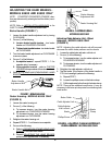
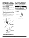
REPLACING WHEELS - MODELS
65900 ONLY (FIGURE 15)
NOTE: Refer to INSTALLATION WARNINGS in the
SAFETY SUMMARY in this instruction sheet.
1. Remove the cap covers from both sides of the wheel.
2. Remove the mounting screw and locknut that secure
the EXISTING wheel to the rollator.
3. Remove EXISTING wheel.
4. Install NEW wheel and secure with NEW mounting
screw and NEW locknut.
5. Install NEW cap covers.
FIGURE 15 - REPLACING WHEELS -
MODEL 65900 ONLY
Cap
Cover
Mounting
Screw
Locknut
Cap
Cover
Wheel
FIGURE 14- REPLACING THE SEAT