


15
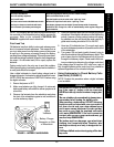
MOTOR BRUSH INSPECTION
(FIGURE 4)
WARNING
Invacare recommends that the following proce-
dures be performed by a qualified service tech-
nician.
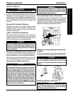
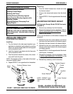
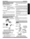
There are two (2) contact brushes on the motors located
under the brush caps on the motor housing. If these caps
are hard to remove they are either overtighened or the motor
has become very hot. Let motors cool. If caps still cannot be
removed, it is recommended that the motor be sent to
Invacare Technical Services for inspection/repair.
NOTE: It is very important to note which way the brush
comes out of the motor. The brush MUST be placed into
the motor exactly the same way to ensure good contact
with the commutator.
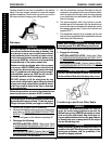
1. Once the motor brush caps have been removed, pull
the brushes out of the motor. The end of the brushes
should be smooth and shiny and the spring should not
be damaged or discolored. If one or both of the brushes
are damaged, only the damaged or worn brushes need
be replaced. It is very important that any time a brush
is replaced, it must be “burned in”. This is accomplished
by running the motor for one hour in each direction
with a half hour break in-between. This should also be
done with little or no load on the motor, i.e., put the rear
of the wheelchair up on blocks and run the wheelchair.
A motor with only one brush replaced will only carry a
small percentage of its rated load capacity until the
NEW brush is burned in.
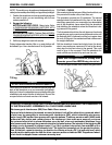
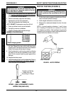
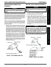
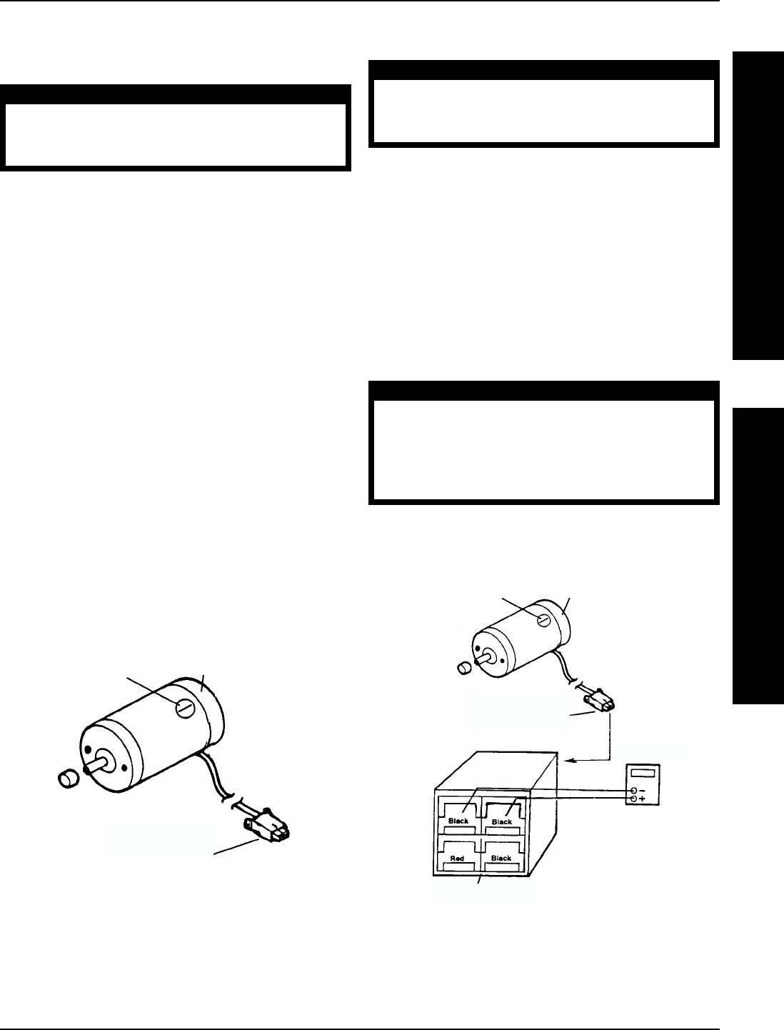
FIGURE 5 - MOTOR LOCK TESTING
End Cap
Brush Cap
Motor End Cap
FIGURE 4 - MOTOR BRUSH INSPECTION
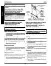
MOTOR LOCK TESTING (FIGURE 5)
WARNING
Invacare recommends that the following proce-
dures be performed by a qualified service tech-
nician.
1. On the four-pin motor connector, locate the side
by side connectors in the black housings.
2. Set the digital multimeter to read ohms.
3. Measure the resistance between the two (2) brake
contacts. A normal reading is 100 ohms (Ω). A
reading of 0 ohms (Ω) or a very high reading; i.e.,
MEG ohms or O.L. (out of limit) indicates a shorted
brake or an open connection respectively. If either
condition exists, it is recommended that the motor
be sent to Invacare Technical Service for inspec-
tion/repair.
CAUTION
A short circuited brake will damage the brake
output section in the controller. DO NOT con-
nect a bad electromechanical brake to a
good controller module. A shorted electrome-
chanical brake MUST be replaced.
NOTE: A bad motor can damage the controller mod-
ule but a bad controller will NOT damage a motor.
Brush Cap
Four (4) Pin Motor Connector
Four (4) Pin Motor Connector
Ohmmeter
Motor Connector
SAFETY INSPECTION/TROUBLESHOOTING PROCEDURE 2
T
R
O
U
B
L
E
S
H
O
O
T
I
N
G
S
A
F
E
T
Y
I
N
S
P
E
C
T
I
O
N