


16
F
O
R
K
/
S
P
R
I
N
G
/
C
R
A
N
K
FORK/SPRING/CRANKPROCEDURE 5
30. Torque the two (2) cap nuts 260-390 inch-pounds.
31. Install the brake arm clamp onto the new fork.
32. Secure the brake arm to the brake arm clamp with
the hex bolt and locknut. Torque to 22-26 inch-pounds.
33. Reinstall the shifting lever onto the seat frame and
secure with the socket screw.
34. Install the tension spring or road crown compensator
onto the new fork. Refer to
EXCELERATOR XLT/
XLT 2000 TENSION SPRING OR ROAD CROWN
COMPENSATOR REPLACEMENT/ADJUSTMENT
in this procedure of the manual.
NOTE: EXCELERATOR XLT BUILT BEFORE 9/99
ONLY- Make sure the shifting cable is between the spring
and the frame.
35. Install the brake assembly onto the new fork. Refer to
the hardware position noted in STEP 8 and tighten
securely with the socket nut.
36. Install the brake handle and half clamp onto the new
fork and secure with the two (2) socket screws.
37. Slide the crank handles onto the new fork.
NOTE: Make sure the sprocket on the crank handles is in
line with the sprocket on the front wheel.
38. Reinstall the chain onto the crank handle sprocket.
39. Move the crank handle to the position determined in
STEP 1 and tighen the two (2) socket screws securely.
8. Note brake assembly hardware position and remove
the brake assembly from the existing fork.
9. Remove the tension spring or road crown compen-
sator from the existing fork. Refer to
EXCELERATOR
XLT/XLT 2000 TENSION SPRING OR ROAD
CROWN COMPENSATOR REPLACEMENT in this
procedure of the manual.
10. Loosen, but do not remove the socket screw that
secures the shifting lever to the seat frame.
11. Remove the hex bolt and locknut that secure the brake
arm to the brake arm clamp.
12. Remove the brake arm clamp from the existing fork.
13. Loosen, but do not remove the two (2) cap nuts that
secure the front wheel to the existing fork.
14. Remove the front wheel from the existing fork.
15. Lay the chain flat.
NOTE: Laying the chain flat will prevent kinks in the chain.
16. Remove the two (2) hex bolts, locknuts and clamps
that secure the footrests to the existing fork.
17. Note the position of the footrests and remove the foot-
rests from the existing fork.
18. Remove the two (2) top nuts that secure the existing
fork to the frame.
19. Note the o-ring and bearing position and remove the
existing fork from the frame.
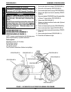
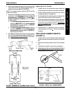
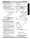
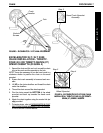
20. Slide the bottom bearing onto the new fork. Refer to
FIGURE 3 for correct orientation.
21. Slide the new fork into the frame.
22. Position the o-ring and bearing on the new fork. Re-
fer to FIGURE 3 for correct orientation.
23. Install the two (2) nuts onto the new fork and tighten
securely. Refer to FIGURE 3 for correct orientation.
24. Position the footrest clamps on the new frame.
25. Install the footrests onto the new fork to the position
noted in STEP 17 and secure with the two (2) hex
bolts and locknuts.
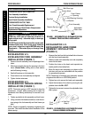
26. Position the chain around the hub of the front wheel.
27. Install the front wheel onto the new fork.
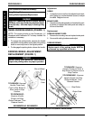
NOTE: Make sure the washer and the non-turn washer
are on the OUTSIDE of the new fork.
28. Line up the projecting ends of the non-turn washer
with the slot in the new fork.
29. Repeat STEPS 27-28 until the projecting ends of the
non-turn washer line up with the slot in the new fork.
EXCELERATOR XLT/XLT 2000
TENSION SPRING OR ROAD
CROWN COMPENSATOR
REPLACEMENT/ADJUSTMENT
NOTE: Excelerator XLTs built before 9/99 have the ten-
sion spring. All Excelerator XLTs built after 9/99 have the
road crown compensator.
NOTE: The tension spring or road crown compensator is
NOT intended to keep the Excelerator XLT/XLT 2000
straight when pedaling but to keep the Excelerator XLT/
XLT 2000 from leaning excessively to one side or an-
other.
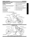
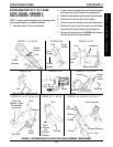
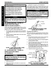
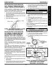
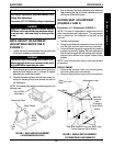
Tension Spring Replacement/Adjustment
(FIGURE 4)
REMOVING TENSION SPRING.
1. Using a medium flat head screwdriver, unhook the
existing tension spring from fork and frame eye bolt.