SECTION 8—ARMS
Zoom
™
300 and Zoom
™
400 42 Part No. 1118395
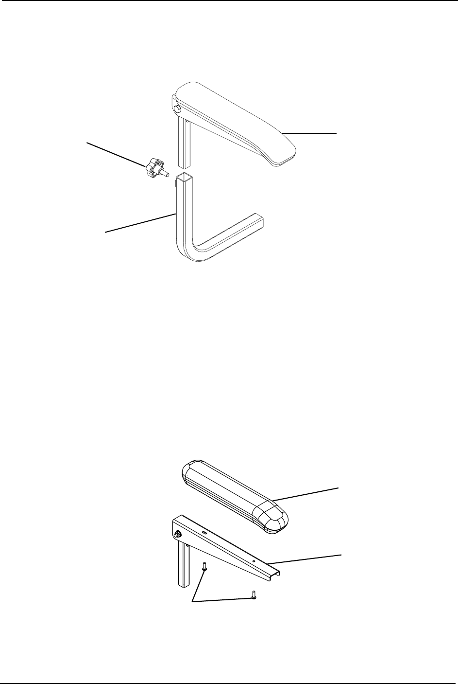
3. Reinstall the lock knob that secures the arm to the arm mounting tube and tighten
securely.
4. Repeat STEPS 1-3 for opposite arm, if necessary.
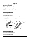
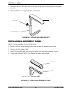
FIGURE 8.3 - ADJUSTING ARM HEIGHT
REPLACING ARMREST PADS
NOTE: For this procedure, refer to FIGURE 8.4.
1. Remove the two (2) mounting screws that secures the armrest pad to arm.
2. Remove the old armrest pad.
3. Install new armrest pad and securely tighten with existing mounting screws.
4. If necessary, repeat STEPS 1-3 to replace the other armrest pad.
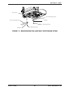
FIGURE 8.4 - REPLACING ARMREST PADS
Arm
Arm Mounting Tube
Lock Knob
Arm Pad
Arm
Mounting Screws


