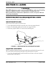
SECTION 8—ARMS
Part No. 1118395 41 Zoom
™
300 and Zoom
™
400
ࣼ CAUTION
The arm can be adjusted to a maximum distance of 4½ inches from the inside of the
arm to the top of the mounting shaft. If the arm is adjusted beyond the maximum
4½ inches, the arm will fall out.
2. Move arm IN or OUT to the desired position.
3. Retighten adjustment knob securely.
4. Measure distance between back and inside of arm.
NOTE: Both arms should be adjusted to the same distance away from the back.
5. Repeat STEPS 1-4 for opposite arm, setting it at the distance determined in STEP 4.
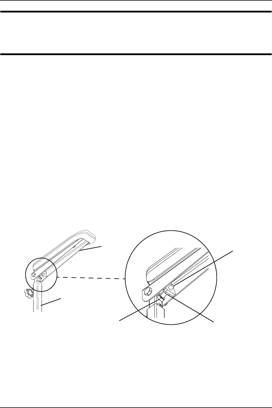
ADJUSTING ARM ANGLE
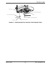
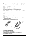
NOTE: For this procedure, refer to FIGURE 8.2.
1. Lift-up the arm.
2. Loosen the jam nut (FIGURE 8.2).
3. Adjust the socket screw up or down to the desired arm angle.
4. Tighten the jam nut.
5. To position the opposite arm at the same angle, count the exposed threads after the
jam nut has been tightened.
6. Set the opposite arm to position determined in STEP 5.
FIGURE 8.2 - ADJUSTING ARM ANGLE
ADJUSTING ARM HEIGHT
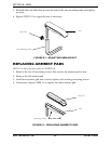
NOTE: For this procedure, refer to FIGURE 8.3.
1. Remove the lock knob that secures the arm to the arm mounting tube.
2. Adjust the arm to desired height.
Count Exposed
Threads
Jam Nut
Adjustment Screw
Arm
Arm Mounting
Tube


