


8
TP970 AND TP9600 SERIES PNEUMATIC THERMOSTATS
75-7134—1
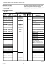
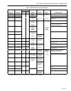
Table 6. TP9600 Thermostat Specifications.
Model No. Description Setpoint Slot Includes Stat.
Single Temperature, Two-Pipe:
TP9600A 1007 DA, Open Windows Open TP970A 2004
TP9600B 1006 RA, Open Windows Open TP970B 2002
TP9603A 1001 DA, Close Windows Closed TP970A 2004
TP9603B 1000 RA, Close Windows Closed TP970B 2002
Day/Night, Two-Pipe:
TP9610A 1006 DA, Open Windows Open TP971A 2003
TP9610B 1005 RA, Open Windows Open TP971B 2001
TP9613A 1000 DA, Close Windows Closed TP971A 2003
TP9613B 1009 RA, Close Windows Closed TP971B 2001
Heating/Cooling, Two-Pipe:
TP9620A 1005 DA, Open Windows Open TP972A 2002
TP9623B 1009 RA, Close Windows Closed TP972B 2002
Single Temperature, One or Two-Pipe:
TP9630A 1004 DA, Open Windows Open TP973A 2076
TP9630B 1003 RA, Open Windows Open TP973B 2066
TP9633A 1008 DA, Close Windows Closed TP973A 2076
TP9633B 1007 RA, Close Windows Closed TP973B 2066
OPERATION
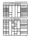
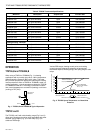
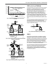
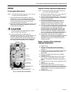
TP970A,B and TP9600A,B
When using a TP970A or TP9600A (Fig. 1) in heating
applications with a normally open valve, a fall in temperature
lowers Branchline Pressure (BLP) to the valve. THis lower
BLP provides proportional valve action matching the existing
load requirements. When a TP970B or TP9600B is used in a
cooling application, a rise in temperature causes the TP970B
or TP9600B to lower BLP. The energy conservation models
limit control temperature to a maximum (heating) or minimum
(cooling) of 72F (24C).
SUPPLY
TP970A,B OR
TP9600A,B
N.O.
M B
M
C3535-1
Fig. 1. TP970A,B and TP9600A,B Typical Operation.
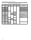
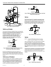
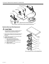
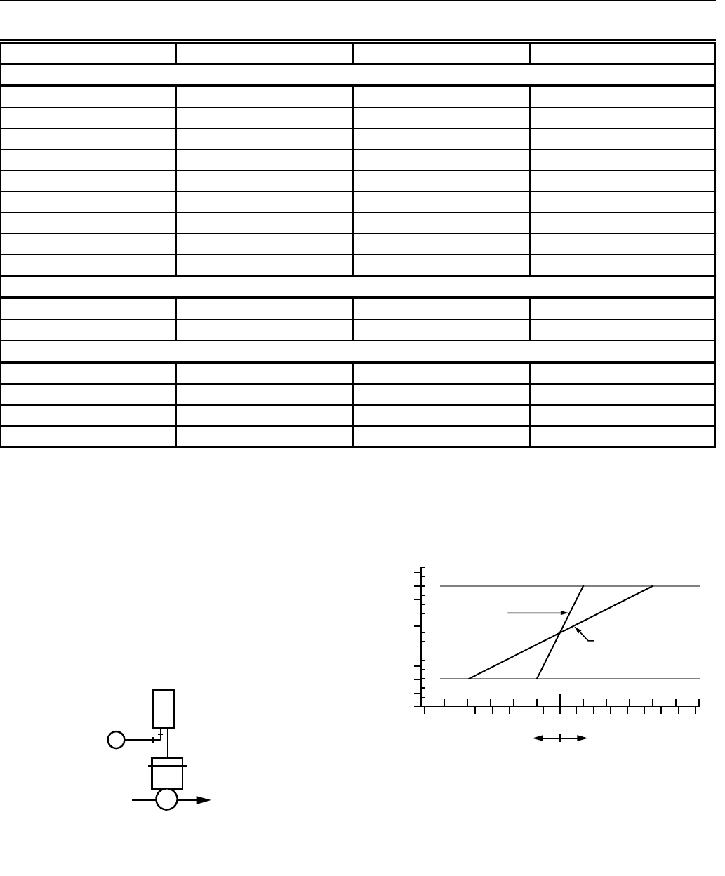
TP970C and D
The TP970C and D with wide throttling range (Fig. 2 and 3)
allow use of heating and cooling valve assemblies with either
selected spring ranges (Fig. 4) or ratio relays (Fig. 5) to
achieve a ZEB range.
Various ZEB ranges, heating control points, and cooling
control points are obtained by selecting the appropriate
thermostat setpoint, throttling range, and spring range or ratio
relays.
15
14
13
12
11
10
9
8
7
6
5
4
3
2
1
(100)
(90)
(80)
(70)
(60)
(50)
(40)
(30)
(20)
(10)
0
15
12.5 10 7.5 5 2.5 1512.5107.552.5
SETPOINT
SETPOINT
(8) (7) (6) (5) (4) (3) (2) (1) (8)(7)(6)(5)(4)(3)(2)(1)
BRANCHLINE PRESSURE—PSI (kPa)
DEVIATION IN SPACE TEMPERATURE—DEGREES F (C)
BELOW SETPOINT ABOVE SETPOINT
C3536
TP970C MINIMUM
THROTTLING RANGE =
5F (2.8C)
TP970C MAXIMUM
THROTTLING RANGE =
20F (11.1C)
Fig. 2. TP970C Space Temperature vs. Branchline
Pressure.