16
TP970 AND TP9600 SERIES PNEUMATIC THERMOSTATS
75-7134—1
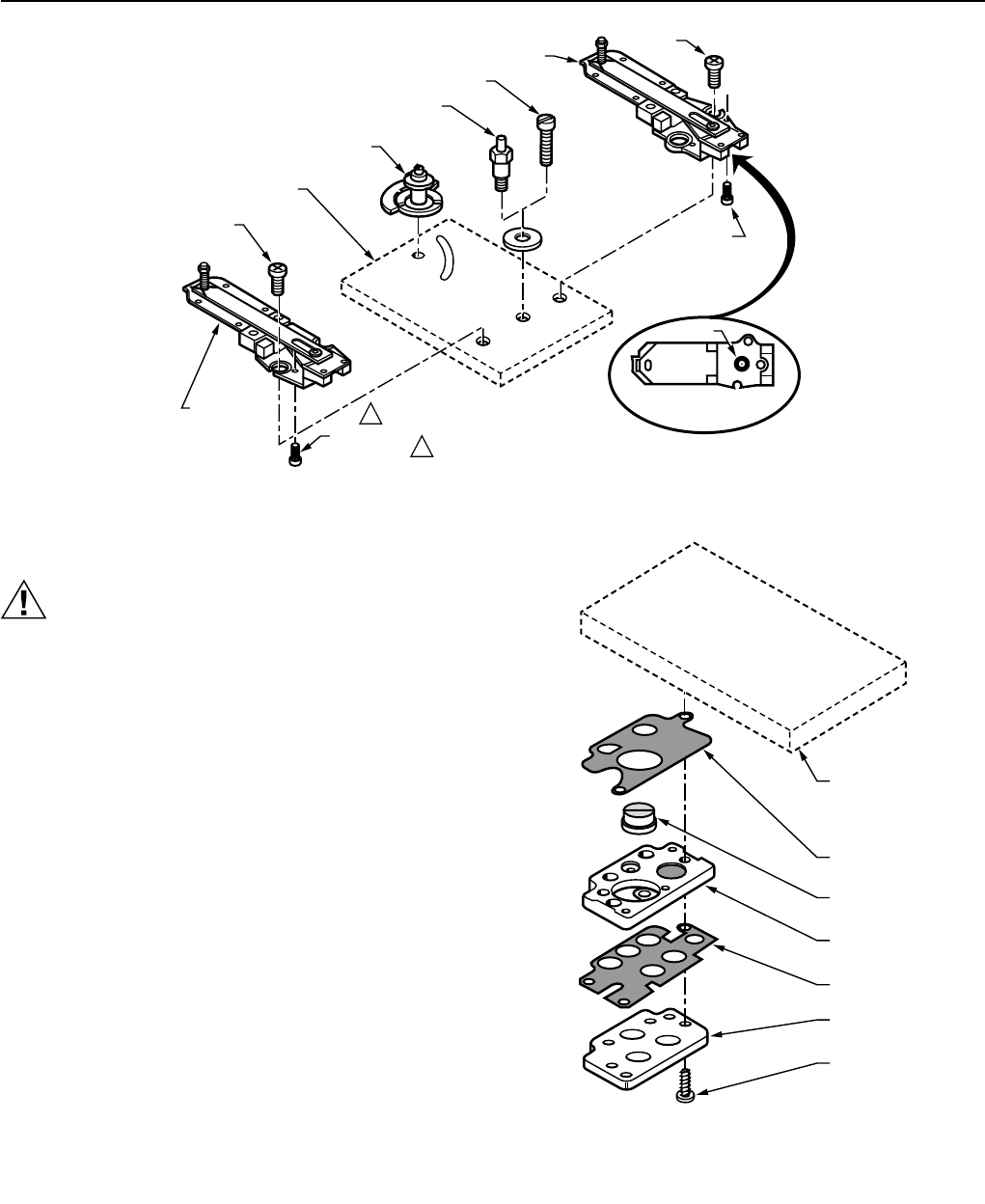
O-RING
NOZZLE, THROTTLING PLATE
AND BIMETAL ASSEMBLY
NOZZLE,
THROTTLING
PLATE AND
BIMETAL
ASSEMBLY
M12208
BOTTOM VIEW OF
BIMETAL ASSEMBLY
SCREW
SCREW
ANTIHUM
SPRING
OR CONE
SCREW
IF THERE IS NO ANTIHUM SPRING/CONE, THERE IS AN
ADHESIVE PAPER DOT ON THE THROTTLING PLATE.
TYPICAL POST
SETPOINT CAM
ASSEMBLY
TYPICAL
PNEUMATIC
ASSEMBLY
SPRING
1
1
Fig. 18. Nozzle, Throttling Plate, Bimetal Assembly Replacement.
Restrictor Block and Filter Replacement
CAUTION
When replacing these parts, use extreme caution to
prevent dirt, dust, or chips from entering various
chambers and openings of the thermostat.
1. Remove the four Phillips head screws which fasten the
restrictor block and filter (Fig. 19) to the back of the
thermostat.
2. Carefully remove the restrictor block assembly (plate,
restrictor, filter, gasket[s]).
3. Replace the restrictor block and filter.
a. Align the appropriate gasket over the
corresponding holes in the thermostat.
b. Insert the filter into the gasket until it bottoms.
c. Position the restrictor block.
d. Align the other gasket on the restrictor block.
e. Position the plate.
f. Replace screws and tighten.
GASKET
TYPICAL
PNEUMATIC
ASSEMBLY
FILTER
RESTRICTOR
GASKET
PLATE
SCREW
M12206
Fig. 19. Restrictor Block and Filter Replacement.


