


TP970 AND TP9600 SERIES PNEUMATIC THERMOSTATS
13
75-7134—1
TP972A and TP9620A
1. With 13 psi (90 kPa) main air pressure, turn the DAY
(SUMMER) (left) calibration screw (Fig. 15) until the
gage reads 0 psi (0 kPa).
2. Turn the calibration screw in the opposite direction until
the gage reads 8 ±1 psi (55 ±7 kPa).
3. With 18 psi (124 kPa) main air pressure, repeat Steps 1
and 2 using the NITE (WINTER) (right) calibration
screw (Fig. 15). The TP972 and TP9620 are now
calibrated.
4. Remove the gage and replace the cover.
TP973A,B and TP9630A,B
If the TP973A, B and TP9630A,B are not properly calibrated
but the remainder of the system is operating properly, turn the
calibration screw until the TP973A, B or TP9630A,B performs
as in Step 2 under CALIBRATION CHECK.
TP974A
Field calibration of the TP974A is not recommended.
TP978A-E
If a TP978 thermostat is not properly calibrated but the
remainder of the system is operating properly, turn the
calibration screw until the thermostat performs as in Step 2
under CALIBRATION CHECK.
TP979A-C
1. Turn the calibration screw (Fig. 15) until the gage reads
0 psi (0 kPa).
2. Turn the calibration screw in the opposite direction until
the gage reads 8 ±1 psi (55 ±7 kPa).
3. The thermostat is now calibrated. The setpoint indicator
and thermometer should be within 1 degree F (0.56
degree C) of each other.
4. Remove the gage and gage adaptor and replace the
cover.
5. Turn the setpoint indicator adjustment until the setpoint
indicator is at the desired setting.
TP979D and E
1. With 13 psi (90 kPa) main line pressure, turn the DAY
(SUMMER) (left) calibration screw (Fig. 15) until the
gage reads 0 psi (0 kPa).
2. Turn the calibration screw in the opposite direction until
the gage reads 8 ±1 psi (55 ±7 kPa).
3. With 18 psi (124 kPa) main air pressure, rotate the
night setpoint dial until the setting agrees with the
indicated temperature.
4. Repeat Steps 1 and 2 using the NITE (WINTER) (right)
calibration screw (Fig. 15). The thermostat is now
calibrated.
5. Remove the gage and replace cover.
Switchover Calibration
Switchover allows for normal supply line fluctuations.
TP971A-E and TP9610A,B
1. Ensure that main line pressure is set to low (13 psi)
pressure requirement.
2. Turn the setpoint indicator adjustment until the setpoint
indicator reads 5 degrees F (2.8 degrees C) below
actual temperature.
3. BLP gage should read 0 psi (0 kPa) (RA) or 13 psi (90
kPa) (DA). If it does not, turn switchover adjustment
screw (Fig. 16) clockwise until it does.
4. Turn the switchover adjustment screw counterclockwise
until the pressure begins to increase (RA) or decrease
(DA). This indicates switchover. Allow the gage to go to
full line pressure (RA) or 0 psi (0 kPa) (DA).
5. Turn the switchover adjustment screw counterclockwise
until pressure decreases to 0 psi (0 kPa) (RA) or
increases to full main line pressure (DA). Turn the
switchover adjustment screw an additional 1/8 to 1/4
turn clockwise. Switchover is calibrated.
TP972A and TP9620A (Cooling, RA;
Heating, DA)
1. Ensure that main line pressure is set to low (13 psi)
pressure requirement.
2. Turn the setpoint indicator adjustment until the setpoint
indicator reads 5 degrees F (2.8 degrees C) below
actual temperature.
3. BLP gage should read 0 psi (0 kPa). If it does not, turn
the switchover adjustment screw (Fig. 16) clockwise
until it does.
4. Turn the switchover adjustment screw counterclockwise
until the pressure begins to increase. This indicates
switchover. Allow the gage to go to full main line
pressure.
5. Turn the switchover adjustment screw counterclockwise
until pressure decreases to 0 psi (switchover point).
Turn the switchover adjustment screw an additional 1/8
to 1/4 turn clockwise. Switchover is calibrated.
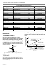
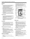
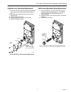
M
P
B
M12211
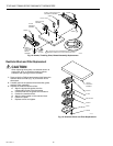
BACK PLATE
SCREWS (4)
THERMOSTAT
MULTISTAGE
FILTER
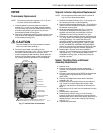
SWITCHOVER
ADJUSTMENT
SCREW
DAY/AUTO
LEVER
Fig. 16. Back View of Thermostat Showing Switchover
Adjustment Screw and DAY/AUTO Lever.