


10
TP970 AND TP9600 SERIES PNEUMATIC THERMOSTATS
75-7134—1
12
M
HI
LO
N.C. N.O.
D/N
MP516C
FAN
P638
G
TP971
C
VALVE
HEATING
COIL
H
120V AC
50/60 HZ
AIR
STREAM
STAT
13/18 PSI
(90/124 kPa)
D/N
MSB K H
FILTER
DISCHARGE AIR
OUTDOOR
AIR
RETURN
AIR
C3541
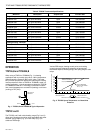
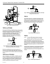
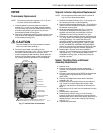
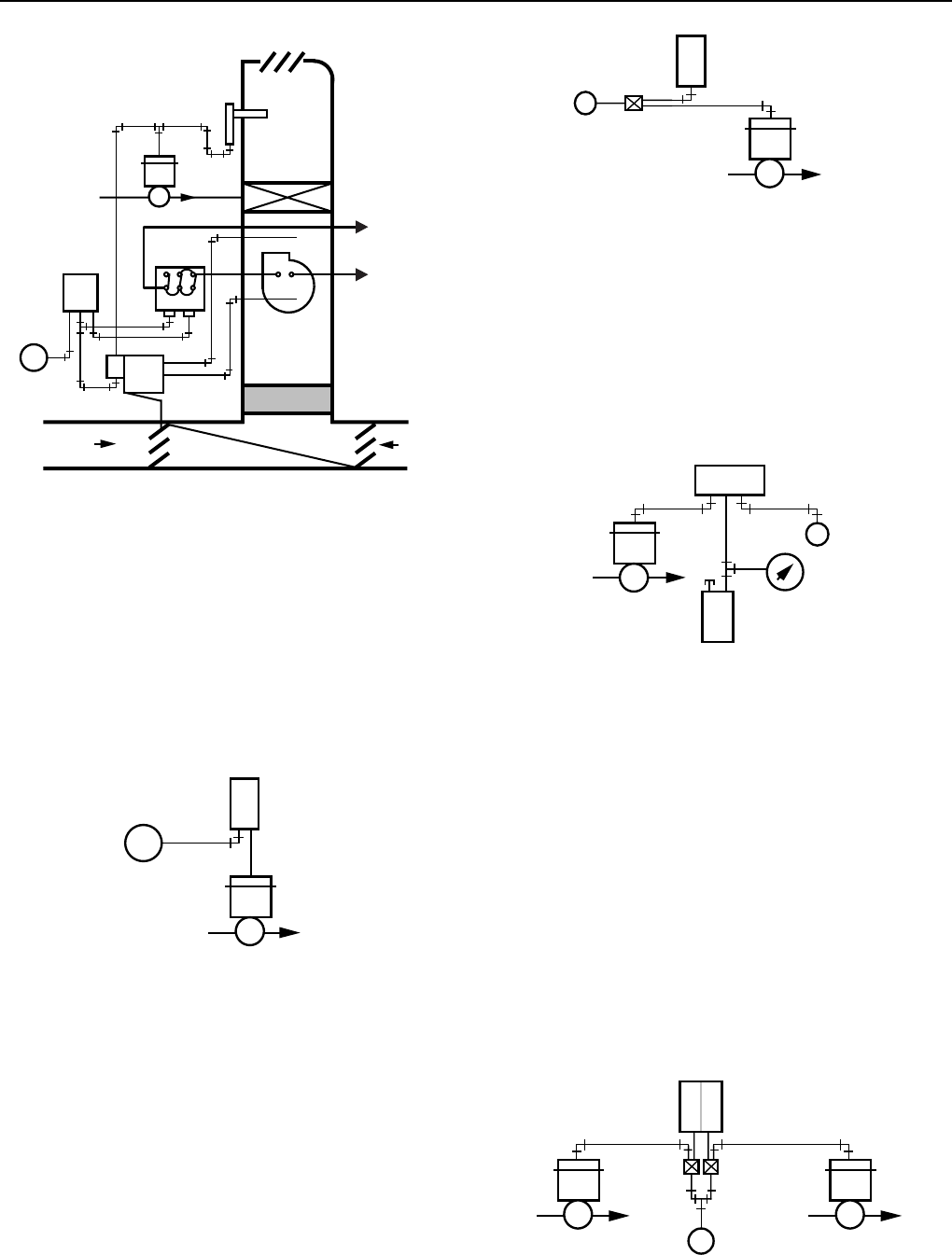
Fig. 7. TP971C Typical Operation.
TP972A and TP9620A
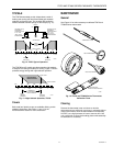
The standard TP972Aand TP9620A is RA for cooling and DA
for heating. A rise in temperature at the TP972Aand TP9620A
with main air pressure at 13 psi (90 kPa) causes the
TP972Aand TP9620A to lower BLP, opening the valve to
control the temperature with chilled water. A fall in
temperature at the TP972Aand TP9620A with main air
pressure at 18 psi (124 kPa) causes the TP972Aand
TP9620A to lower BLP, opening the valve to control the
temperature with hot water (Fig. 8).
TP972A OR
TP9620A
13 PSI
(90 kPa) RA
18 PSI
(124 kPa)
DA
N.O.
M B
S/W
HOT WATER/CHILLED
WATER SUPPLY
C3542-1
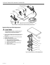
Fig. 8. TP972A and TP9620A Typical Operation with a
Normally Open Water Valve Assembly.
Models are available that limit the cooling setpoint to a
minimum of 75 or 78F, the heating setpoint to a maximum of
72 or 75F. They work with 13/18, 16/21, 25/20, 19/14, or 20/
25 psi changeover. Some models are DA for both cooling and
heating.
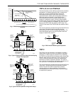
TP973A,B and TP9630A,B
A fall in temperature at the TP973A or TP9630A causes the
TP973A or TP9630A to lower BLP, providing proportional
control of existing load requirements for heating (Fig. 9). A
rise in temperature at the TP973B or TP9630B causes the
TP973B or TP9630B to lower BLP, providing proportional
control of existing load requirements for cooling.
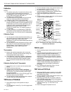
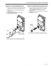
Fig. 9. TP973A and TP9630A Typical Operation, One-Pipe
Using External Restriction.
TP974A
The TP974A Sensor (Fig. 10) provides a pneumatic output
signal of 3 to 15 psi (21 to 103 kPa) in direct relation to the
sensed temperature, allowing direct and remote readout of
the temperature. An RP908 or RP920 Controller is used with
the TP974A to convert the output into a usable signal to
operate a pneumatic valve, damper, or other equipment.
TP973A OR
TP9630A
M
N.O.
HOT WATER OR
STEAM SUPPLY
C3543-1
TP974
VALVE
TEMP
GAGE
4 8 9
2 3 1
M
RP920
C3544A
MB
Fig. 10. TP974 Typical Operation.
TP978E
NOTE: To vary the ZEB between heating and cooling
operation, adjust the setpoints on the TP978E.
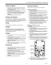
A fall in temperature within the cooling range at the TP978E
causes the TP978E to increase the BLP of the cooling
element. This action proportionally closes the normally open
cooling valve (Fig. 11) to maintain the temperature set on the
high range portion of the TP978E. The normally open heating
valve is held closed by the high BLP on the DA side of the
TP978E.
A continued fall in temperature, into the heating range at the
TP978E, lowers the BLP of the heating element. This action
proportionally opens the normally open heating valve to
maintain the temperature set on the low range portion of the
TP978E.
DA RA
TP978E
M
HEATING
VALVE
COOLING
VALVE
H C
N.O. N.O.
C3545
EXTERNAL
RESTRICTORS
0.005
Fig. 11. TP978A Typical Operation.