


TP970 AND TP9600 SERIES PNEUMATIC THERMOSTATS
15
75-7134—1
REPAIR
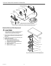
Thermometer Replacement
NOTE: The following procedure requires a 1/4-in. (6 mm)
nut driver and a small screwdriver.
1. Insert the blade of a small screwdriver under the
bimetal (Fig. 17) and pry up. Older style thermostats
have a locking ring. Insert the blade between the ring
and white nylon bushing and pry the ring from the
thermometer bimetal mounting post.
2. Remove the bimetal and bushing by lifting the top of the
plate to which the scaleplate is attached, near the hex
of the bimetal mounting post.
CAUTION
The new bimetal can be easily distorted if extreme
care is not used when handling it.
3. Press the new bimetal and bushing into the
thermometer post using a 1/4-in. (6 mm) nut driver over
the bobbin. Allow the bimetal to cool down to the
ambient temperature after handling. Slowly rotate the
bushing until the thermometer pointer is aligned with
the existing ambient temperature on the scaleplate.
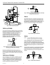
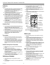
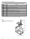
ANTIHUM
SPRING/CONE
BIMETAL
SETPOINT
INDICATOR
SCALEPLATE
MOUNTING POSTS
SCALEPLATE
LOCKING TABS
SETPOINT INDICATOR
ADJUSTMENT
IF THERE IS NO ANTIHUM SPRING/CONE, THERE IS AN
ADHESIVE PAPER DOT ON THE THROTTLING PLATE.
1
1
M11384
Fig. 17. Internal View of Thermostat.
Setpoint Indicator Adjustment Replacement
NOTE: Dual temperature thermostats require removal of
only one of the bimetal assemblies.
1. Remove the setpoint indicator (Fig. 17) by prying it off
the indicator post with a small screwdriver.
2. Remove the thermometer bimetal (Fig. 17) by lifting the
plate to which the scaleplate is attached, at the hex of
the bimetal mounting post.
3. Bend the scaleplate locking tabs (Fig. 17) up and
compress the scaleplate mounting posts (Fig. 17)
together with the thumb and forefinger to free the
scaleplate from the holding notches in the post.
4. Remove and replace setpoint indicator adjustment (Fig.
17), using caution not to damage or distort the bimetal
sensing element(s). On models with DAY-NITE
temperature setpoint wheel (located under the right
sensing element), see the NOZZLE, THROTTLING
PLATE, and BIMETAL ASSEMBLY REPLACEMENT
section for removal of the bimetal and DAY-NITE scale
prior to removing the setpoint indicator adjustment.
5. Reassemble in reverse order and recalibrate if
required. It is not necessary to re-engage the scaleplate
locking tabs (Fig. 17) in the holding notches of the
scaleplate mounting posts, as they are primarily for
shipping purposes.
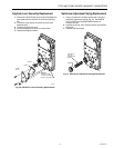
Nozzle, Throttling Plate and Bimetal
Assembly Replacement
1. Remove cover.
2. Remove the thermometer bimetal, temperature
indicator, and scaleplate as previously described, if
applicable.
3. Unscrew center holding screw (TP978) or thermometer
mounting post using Thermostat Tool CCT735A
(MQT735A).
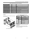
4. Remove the Phillips head screw and the defective
assembly (Fig. 18).
5. Replace with new assembly being sure the rubber O-
ring, if used, is properly aligned around the nozzle
opening in the recess on the bottom of the aluminum
block.
6. Insert spring cone (if used) into new assembly from the
bottom.
7. Reassemble the thermostat.
8. Check that the antihum spring or cone (if used) is
properly positioned so that the spring just touches the
throttling plate and the base of the spring (larger end) is
seated properly in the recess of the spring mounting
hole (Fig. 17).
9. Calibrate the thermostat.