


12
TP970 AND TP9600 SERIES PNEUMATIC THERMOSTATS
75-7134—1
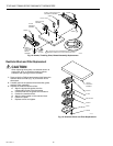
Calibration
NOTES:
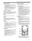
1. The antihum spring (Fig. 15) must be free. Be sure the
spring just touches the throttling plate and is not
wedged against it (does not apply to all TP970C and D
or any TP970 series starting with 2000, i.e.,
TP972A2143 and TP9600 series).
2. The thermostats are very sensitive and should not be
heated by excessive handling during calibration.
3. Calibration of the TP974 is not recommended.
4. To check calibration or to recalibrate the Limited Control
Range (LCR) thermostats, the space temperature must
be 78F (26C) or above for cooling applications, and 72
or 68F (22 or 20C) or below for heating applications,
depending on the model. TP972A1119 and
TP972A1127 are 68F (20C). The setpoint limitation is
nonadjustable.
5. To check calibration or to recalibrate the TP978 ZEB
thermostats, measure actual room temperature with a
test thermometer. The 75F (24C) limit is nonadjustable.
Calibration Check
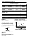
1. Turn the setpoint indicator adjustment down (DA) or up
(RA) until the setpoint indicator reads 5 degrees F (2.8
degrees C) below (DA) or above (RA) room
temperature. The BLP at the thermostat should build up
within 30 seconds.
2. Turn the setpoint indicator adjustment up (DA) or down
(RA) slowly. The thermostat should begin to bleed off
audibly between 1 and 3 degrees F (0.56 and 1.7
degrees C) below (DA) or above (RA) room
temperature.
Thermometers
1. Measure the ambient temperature with an accurate
thermometer. Compare the thermometer reading with
the thermostat thermometer reading.
2. If the difference is more than 1 degree F (0.56 degree
C), use the Thermometer Calibration Tool MQT970 to
twist the thermostat thermometer calibration bobbin
(Fig. 15) until the thermostat thermometer reading is
correct.
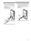
Calibration Set-Up (For All Thermostats)
1. Start with the main air pressure at the recommended
setting.
2. Remove the thermostat cover.
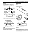
3. All thermostats except the TP978E: Install Gage
305965 (0 to 30 psi [0 to 207 kPa]) with Gage Adapter
315161A (Fig. 14) into the branchline pressure gage
tap (except TP978E).
TP978E: Install a 0 to 30 psi (0 to 207 kPa) gage in the
branchline remote from the TP978E.
4. Turn the setpoint indicator adjustment until the setpoint
indicator reads the existing temperature.
TP970A,B and TP9600A,B
1. Set throttling range to value specified on the job
drawing.
2. Turn the calibration screw (Fig. 15) until the gage reads
0 psi (0 kPa).
3. Turn the calibration screw in the opposite direction until
the gage reads 8 ±1 psi (55 ±7 kPa).
4. The TP970 and TP9600 are now calibrated. The
setpoint indicator and thermometer should be within 1
degree F (0.56 degree C) of each other.
5. Remove the gage and gage adaptor and replace the
cover.
6. Turn the setpoint indicator adjustment until the setpoint
indicator is at the desired setting.
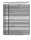
7060 80 90
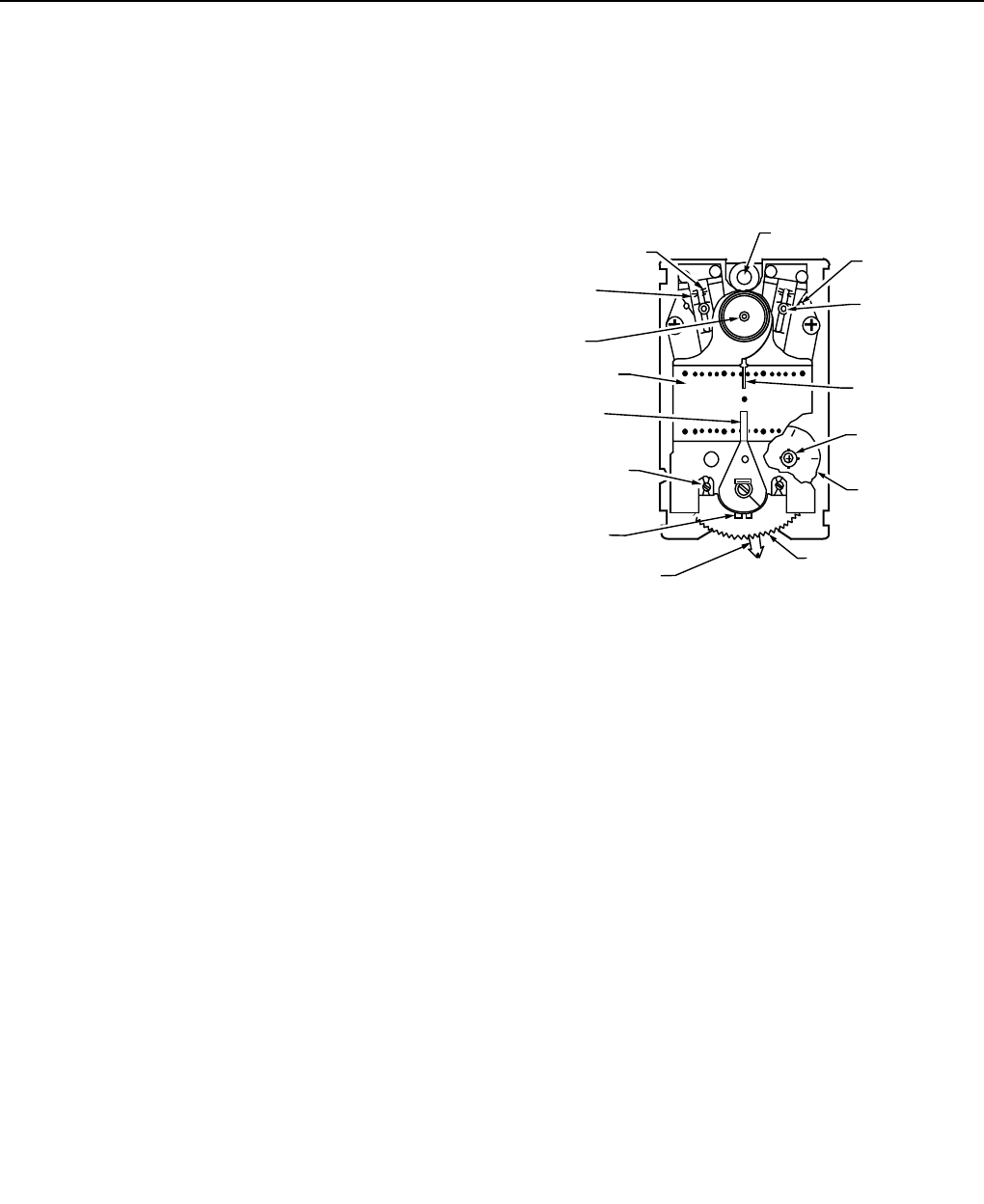
ANTIHUM
SPRING (2)
THROTTLING
RANGE
ADJUSTMENT (2)
(NITE/WINTER)
SETPOINT DIAL
(NITE/WINTER)
THERMOMETER
CALIBRATION
BOBBIN
SETPOINT
INDICATOR
(NITE/WINTER)
SETPOINT
INDICATOR
CALIBRATION
SCREW
(DAY/SUMMER)
DAY/AUTO LEVER
(TP971 ONLY)
SETPOINT INDICATOR
ADJUSTMENT
C3946-3
5
5
5
6
7
SCALEPLATE
MAX
MAX
THROTTLING RANGE
SCALE (2)
(DAY/SUMMER)
THROTTLING
PLATE (2)
GAGE TAP
NOTE: NOT ALL ADJUSTMENTS ARE ON ALL THERMOSTATS.
TEMPERATURE
INDICATOR
STOPS
TEMPERATURE
SETTING
Fig. 15. Thermostat Front View, Cover Off, Showing
Controls and Indicators.
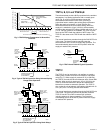
TP970C and D
1. Set the throttling range to value specified on the job
drawing.
2. Check the mechanical throttling range by turning the
setpoint indicator adjustment to determine the
difference in setpoint indicator readings when BLP
reads 3 psi (21 kPa) and 13 psi (90 kPa). It may be
necessary to turn the calibration screw to obtain this
measurement.
3. Reset the throttling range to within ±2 degrees F (±1.1
degrees C) of the specified throttling range for accurate
control. If either the throttling range adjustment or
calibration screw were changed, recalibrate the
thermostat.
4. See TP970A and B, beginning at Step 1, for the
balance of TP970C and D calibration.
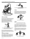
TP971A-E and TP971A,B
1. With 13 psi (90 kPa) main air pressure, turn the DAY
(SUMMER) (left) calibration screw (Fig. 15) until the
gage reads 0 psi (0 kPa).
2. Turn the calibration screw in the opposite direction until
the gage reads 8 ±1 psi (55 ±7 kPa).
3. With 18 psi (124 kPa) main air pressure, rotate the
NITE (WINTER) setpoint dial until the setting agrees
with the indicated temperature.
4. Repeat Steps 1 and 2 using the NITE (WINTER) (right)
calibration screw (Fig. 15). The TP971 is now
calibrated.
5. Remove the gage and replace the cover.