


Overview
3A0590G 9
Overview
The left side of the mix manifold is intended for the major
volume material, or the higher viscosity material if using a
1:1 volume mix. This side is referred to throughout the
manual as the resin side or “A” side.
The right side is referred to as the Hardener side or “B”
side. The “B” side incorporates an adjustable restrictor for
balancing the system back pressure and flow.
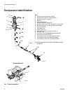
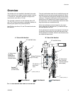
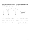
See FIG. 2 to view flow of “A” and “B” material inside the
Mix Manifold.
The resin and hardener enter the mix manifold through the
manifold inlet ports and spring loaded carbide ball checks.
The “A” material flows through the manifold to the material
outlet port. The injector tube creates a hollow stream of “A”
material for the “B” material to fill once the hardener exits
the injector tube. The resin and hardener material mix after
they have left the mix manifold block (B).
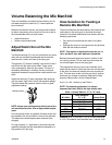
When the manifold is mounted remote from the propor-
tioner, adjust the “B” side restrictor (F) to balance the sys-
tem back pressure and flow.
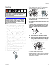
On the standard mix manifold, mixed material is flushed out
by sending a flush solvent through the B side center tube.
On the quickset mix manifold, solvent is also flushed across
the A side fluid check valve.
FIG. 2: Cross-Section Side Views of A and B Flow
“B” Side of Mix Manifold“A” Side of Mix Manifold
Mixed Material A Side Material B Side Material
F
H
H
Solvent Fluid Inlet
r_258987_3a0420_2a
r_258987_3a0420_3a
Carbide
Check Valve
F
“B” Inlet Ball Valve
“A” Inlet Ball Valve
(on each side)
“B” side solvent
flush inlet after
restrictor (Used o
n
both models)
“A” side solvent
flush inlet
across check
ball added on
Quickset model.
(on “B” side)
“B” side flow
after check
valve