Installation
10 3A0590G
Installation
For assistance in setting up a plural component sprayer,
contact your Graco distributor, to ensure that you select
the proper type and size equipment for your system.
See illustration in F
IG. 1 on page 8.
Fluid Inlets
The A and B fluid inlets (A and B) are equipped with 1/2
npt(f) ball valves. Connect 1/2 in., 3/8 in., or 1/4 in.
npsm(f) fluid hoses with adapter nipples as needed. See
brochure 339361 for high pressure hose and fitting part
numbers.
NOTE: If the manifold is remote, the hoses must be
properly sized and balanced. See Volume Balancing
the Mix Manifold on page 15 for more remote setup
information.
Solvent Inlet
Connect the solvent supply line (D) from the solvent
pump to the 1/4 npt(m) solvent inlet valve (C), or inlet
tee on the Quickset model.
NOTE: Use a Graco approved grounded hose rated
to withstand the maximum fluid working pressure of
the solvent pump. The hose core must be chemi-
cally compatible with the solvent being used, such
as nylon or PTFE.
Fluid Outlet
Connect the outlet to two primary static mixer tubes (J),
with mixer elements (M), to the mix hose (N), cleanup
mixer (J), whip hose (K), and spray gun (L).
Add mixed material hose as necessary between the mix
hose and cleanup mixer.
Mounting
Remote Mix Manifold
The mix manifold can be removed from the proportioner
and mounted closer to the gun. This reduces the volume
of mixed material and flush solvent for quick setting
materials (less than 10 minute pot life). See Volume
Balancing the Mix Manifold on page 15 for more
remote setup information.
Use Remote Mix Manifold Carriage 262522 for in-line
hose mount locations. The carriage protects the mani-
fold and valves from accidental operation which could
cause a plugged line.
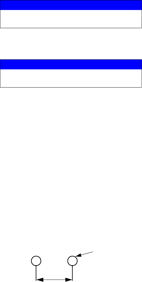
Bare Manifold
To mount the bare manifold, drill two holes in the mount-
ing surface, and secure with the two 1/4-20 screws (28).
NOTICE
To prevent creating a flare on the mixer tube, do not
use a union swivel end on the mix tube inlet.
NOTICE
Never split the flow to multiple guns until the two flu-
ids are mixed after the mix manifold assembly.
1.1 in. (27.94 mm)
9/32 diameter


