


9
Use of a condensate removal pump is permitted when nec-
essary. This condensate pump should have provisions for
shutting off the control voltage should a blocked drain occur.
A trap must be installed between the unit and the conden-
sate pump.
IMPORTANT NOTE: The evaporator coil is coated with oils
that may dissolve styrofoam and certain types of plastics.
Therefore, a removal pump or float switch must not contain
any of these materials.
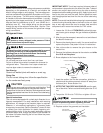
Tip: Priming the “P” trap may avoid improper draining at the
initial installation and at the beginning of the cooling season.
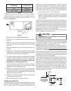
When coils are installed above ceilings, or in other locations
where damage from condensate overflow may occur, it is
MANDATORY to install a field fabricated auxiliary drain pan
under the coil cabinet enclosure. Drain lines from the auxiliary
pan must be installed and terminated so that the homeowner
can see water discharges.
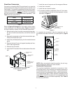
Achieve 2% Low Leakage Rate
Ensure that the Neoprene gasket with PSA remains intact on
all surfaces that the access panels are secured to. These
surfaces are the entire length of the wrapper and areas be-
tween the upper tie plate, upper and lower access panels.
Be sure that upper access panel breaker insert gasket is in-
tact and also flowrator gasket is installed on the lower ac-
cess panel. An additional drain hole cover is required.
ASPF Motor
The ASPF air handler features an energy efficient blower
motor. The motor is a constant torque motor with very low
power consumption. The motor is energized by 24 VAC. Ad-
just the CFM by changing the 24 VAC leads to the desired
speed on the terminal block.
The ASPF motor blower speed is programmed to deliver ad-
equate airflow at rated external static pressure and with 60
second off time delay. For details, refer to the specification
sheet applicable to your model.
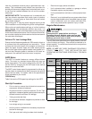
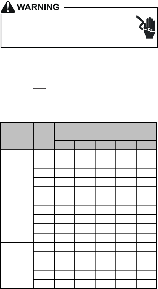
CFM Delivery
Table 9 shows the CFM speed tap settings for the ASPF.
Start-Up Procedure
• Prior to start-up, ensure that all electrical connections
are properly sized and tightened.
• All panels must be in place and secured. For Air Tight
application, neoprene gasket must be positioned at pre-
scribed locations to achieve 2% leakage.
• Tubing must be leak free.
• Unit should be elevated, trapped and pitched to allow
for drainage.
• Low voltage wiring is connected.
• Auxiliary drain is installed when necessary and pitched
to allow for drainage.
• Drain pan and drain tubing has been leak checked.
• Return and supply ducts are sealed.
• Unit is elevated when installed in a garage or where
flammable vapors may be present.
• Unit is protected from vehicular or other physical dam-
age.
• Return air is not obtained from any areas where there
may be objectionable odors, flammable vapors or prod-
ucts of combustion such as carbon monoxide (CO),
which may cause serious personal injury or death.
Regular Maintenance
HIGH VOLTAGE!
Disconnect ALL power before servicing or
installing this unit. Multiple power sources may
be present. Failure to do so may cause property
damage, personal injury or death.
The only item to be maintained on a regular basis by the user
is the circulating air filter(s). Filter should be cleaned or re-
placed regularly. A certified service technician must perform
all other services.
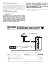
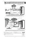
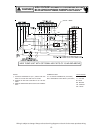
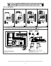
NOTE: DO NOT USE THESE DIAGRAMS FOR MODELS
OTHER THAN ASPF. SEE INSTALLATION AND
OPERATING INSTRUCTIONS SPECIFICALLY FOR EACH
MODEL.
Motor
Speed
Tap 0.1" 0.2" 0.3" 0.4" 0.5"
1 700 670 650 595 510
2 820 785 765 745 705
ASPF183016 3 920 900 850 840 815
4 1075 1055 1015 975 960
5 1130 1115 1085 1040 1000
1 1060 865 600 515 420
2 1105 910 795 745 690
ASPF313716 3 1165 1070 1020 960 915
4 1285 1240 1195 1140 1100
5 1435 1395 1350 1315 1265
1 1445 1275 1175 940 855
2 1545 1405 1325 1260 1145
ASPF426016 3
1660 1610 1555 1490 1415
4
1905 1870 1810 1750 1695
5
2115 2070 2000 1965 1915
CFM deliverd
against External Static Pressure
Model
Table 9