


5
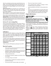
HIGH VOLTAGE!
Failure to do so may cause property damage,
personal injury or death.
Disconnect ALL power before servicing.
Multiple power sources may be present.
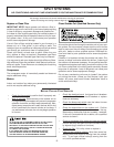
HIGH VOLTAGE!
To avoid property damage, personal injury or death
due to electrical shock, this unit MUST have an
electrical ground. The
electrical ground circuit may consist of an
appropriately sized electrical wire connecting the
ground lug in the unit control box to the building
electrical service panel.
Other methods of grounding are permitted if performed
in accordance with the National Electric Code
(NEC)/American National Standards Institute
(ANSI)/National Fire Protection Association (NFPA) 70
and local/state codes. In Canada, electrical grounding
is to be in accordance with the Canadian Electric Code
(CSA) C22.1.
uninterrupted, unbroken
Building Electrical Service Inspection
This unit is designed for single-phase electrical supply. DO
NOT OPERATE ON A THREE-PHASE POWER SUPPLY.
Measure the power supply to the unit. The supply voltage
must be in agreement with the unit nameplate power require-
ments and within the range shown in Table 5.
Nominal Input Minimum Voltage Maximum Voltage
208/240 187 253
Table 5
Wire Sizing
Wire size is important to the operation of your equipment.
Use the following check list when selecting the appropriate
wire size for your unit.
• Wire size must carry the Minimum Circuit Ampac-
ity (MCA).
• Refer to the NEC (USA) or CSA (Canada) for wire siz-
ing. The unit MCA for the air handler and the optional
electric heat kit can be found on the unit Series and
Rating Plate.
• Wire size allows for no more than a 2% voltage drop
from the building breaker/fuse panel to the unit.
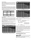
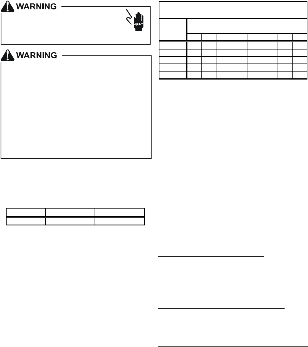
Refer to the latest edition of the National Electric Code
or in Canada the Canadian Electric Code when deter-
mining the correct wire size. The following table shows
the current carrying capabilities for copper conductors
rated at 75
o
C with a 2% voltage drop. Use Table 6 to
determine the voltage drop per foot of various conduc-
tors.
10 15 20 25 30 35 40 45
14 75 50 37 NR NR NR NR NR
12 118 79 59 47 NR NR NR NR
10 188 125 95 75 63 54 NR NR
8 301 201 150 120 100 86 75 68
6 471 314 235 188 157 134 118 110
*Based on NEC 1996
Maximum Allowable Length in Feet
to Limit Voltage Drop to 2%*
Minimum Circuit Ampacity (MCA)
Wire Size
(AWG)
Table 6
Maximum Overcurrent Protection (MOP)
Every installation must include an NEC (USA) or CEC
(Canada) approved overcurrent protection device. Also,
check with local or state codes for any special regional re-
quirements.
Protection can be in the form of fusing or HACR style circuit
breakers. The Series and Rating Plate can be used as a
guide for selecting the MAXIMUM overcurrent device.
NOTE: Fuses or circuit breakers are to be sized larger
than the equipment MCA but not to exceed the MOP.
Electrical Connections – Supply Voltage
USE COPPER CONDUCTORS ONLY.
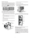
A knockout is provided on the air handler top panel or side to
allow for the entry of the supply voltage conductors. If the
knockouts on the cabinet sides are used for electrical con-
duit, an adapter ring must be used in order to meet UL1995
safety requirements. An NEC or CEC approved strain relief
is to be used at this entry point. The wire is to be sized in
accordance with the “Electrical Wire and MOP” section of
this manual. Some areas require the supply wire to be en-
closed in conduit. Consult your local codes.
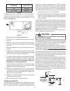
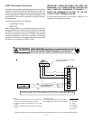
Air Handler Only (Non-Heat Kit Models)
The building supply connects to the stripped black and red
wires contained in the air handler electrical compartment cav-
ity. A ground screw is also contained in this area. Attach the
supply wires to the air handler conductors as shown in the
unit wiring diagram using appropriately sized solderless con-
nectors or other NEC or CEC approved means.
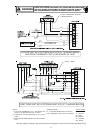
Air Handler With Non-Circuit Breaker Heat Kits
A terminal block is provided with the HKR kit to attach the
power supply and air handler connections. Follow the HKR
Installation Manual and wiring diagram for complete wiring
details.
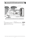
Air Handler With Heat Kits Containing a Circuit Breaker
HKR models with a “C” suffix contain a circuit breaker(s).
The air handler has a plastic cover on the access panel that
will require either one or both sections to be removed to al-
low the heat kit circuit breaker(s) to be installed. See the
HKR Installation Instructions for further details. The air han-
dler wires and supply wires are installed directly onto the HKR
circuit breaker(s) as shown in the HKR Installation Manual
and wiring diagram.