


4
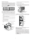
Return Ductwork
DO NOT TERMINATE THE RETURN DUCTWORK IN AN
AREA THAT CAN INTRODUCE TOXIC, OR OBJECTION-
ABLE FUMES/ODORS INTO THE DUCTWORK. The return
ductwork is to be introduced into the air handler bottom (upflow
configuration).
Return Air Filters
Each installation must include a return air filter. This filtering
may be performed at the air handler or externally such as a
return air filter grille. Air handlers mounted in the downflow
orientation, including “B” series, require external filtering. A
washable filter is available as an accessory. To ensure opti-
mum performance frequent filter cleaning is advised. Refer
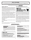
to Table 1 for the appropriate filter.
ASPF Filter Number Qty Required
3137
4260
FIL 48-61 1
1830 FIL 36-42 1
Table 1
Electric Heat
Refer to this manual in combination with the instructions pro-
vided with the heat kit for the correct installation procedure.
The air handlers listed in this manual do not have factory
installed electric heat. Electric heat is available as an acces-
sory. If installing this option, the ONLY heat kits that can be
used are the HKR series.
NOTE: The Amana® brand EHK, ECB, EDB, and EDK kits
are NOT approved for use with these air handlers.
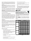
The heating mode temperature rise is dependent upon the
system airflow, the supply voltage, and the heat kit size (kW)
selected. Use Tables 2, 3, and 4 to determine the tempera-
ture rise (
º
F).
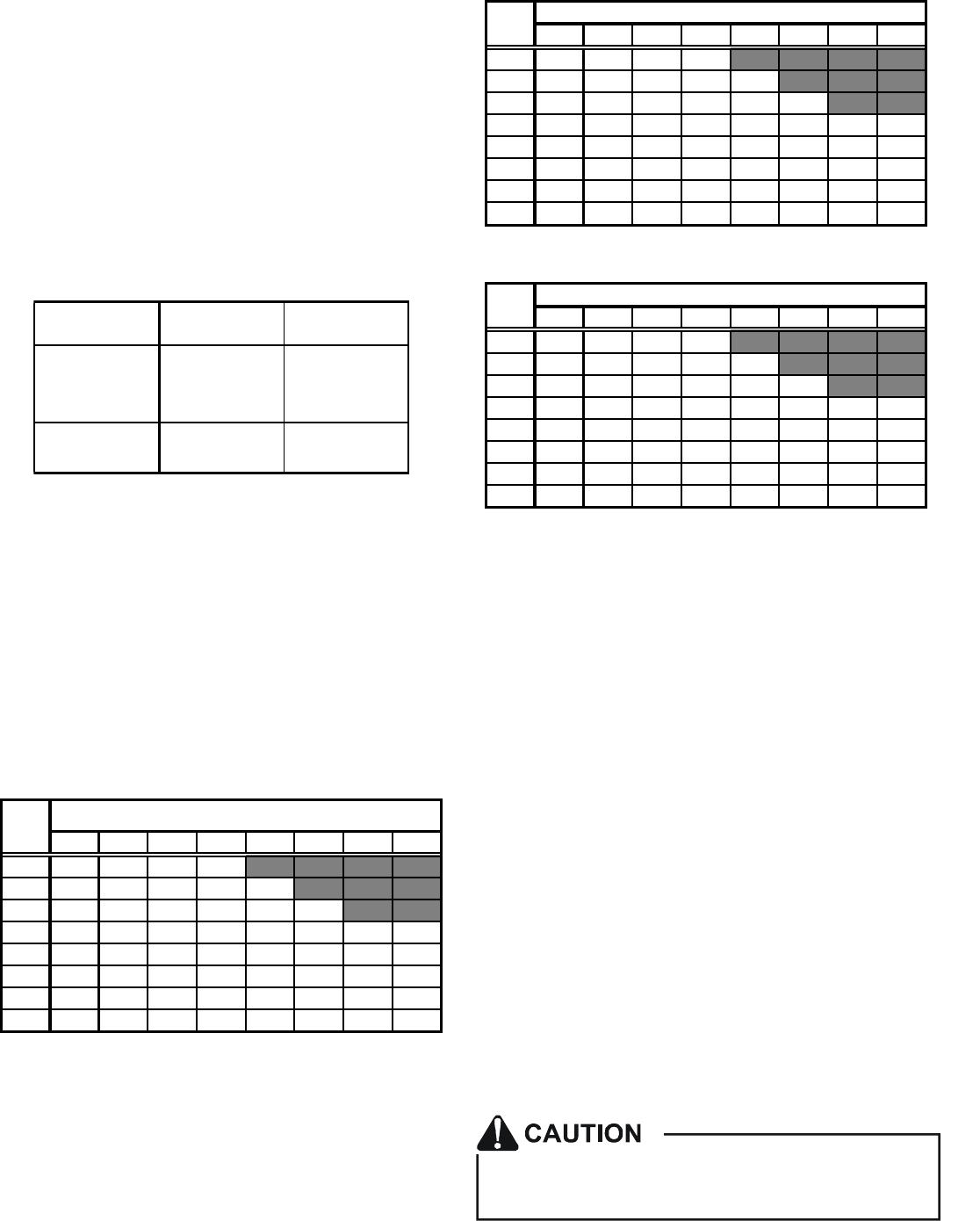
356810152021
600 18 28 35 41
800 13 21 26 31 42
1000 11 17 21 25 34 50
12009 14182128425662
14008 12151824364853
16007 10131521314246
1800 6 9 12 14 19 28 37 41
2000 5 8 11 12 17 25 34 37
HEAT KIT NOMINAL kW
CFM
Table 2
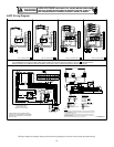
230/1/60 Supply Voltage - Temperature Rise Table °F
356810152021
600 17 27 34 39
800 13 20 25 30 40
1000 10 16 20 24 32 48
12008 13172027405359
14007 11141723344651
16006 10131520304044
1800 6 9 11 13 18 27 36 39
2000 5 8 10 12 16 24 32 35
CFM
HEAT KIT NOMINAL kW
Table 3
220/1/60 Supply Voltage - Temperature Rise Table °F
356810152021
600 16 25 32 37
800 12 19 24 38 38
1000 10 15 19 22 30 46
12008 13161925385156
14007 11141622334348
1600 6 9 12 14 19 28 38 42
1800 5 8 11 12 17 25 34 37
2000 5 8 10 11 15 23 30 34
CFM
HEAT KIT NOMINAL kW
Table 4
208/1/60 Supply Voltage - Temperature Rise Table °F
NOTE: For installations not indicated above the following
formula is to be used:
TR = (kW x 3412) x (Voltage Correction) x 1.08 / CFM
Where: TR = Temperature Rise
kW = Heater Kit Actual kW
3412 = Btu per kW
Voltage Correction =.96 (230 Supply Volts)
=.92 (220 Supply Volts)
=.87 (208 Supply Volts)
1.08 = Constant
CFM = Measured Airflow
NOTE: The Temperature Rise Tables can also be used to
determine the air handler airflow delivery. When using these
tables for this purpose set the room thermostat to maximum
heat and allow the system to reach steady state conditions.
Insert two thermometers, one in the return air and one in the
supply air. The temperature rise is the supply air temperature
minus the room air temperature.
Use HKR specification sheets to determine the HKR avail-
able for a given air handler.
HKR Installation
Follow instructions listed in Installation and Operating Instruc-
tions shipped with the heat kit.
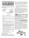
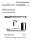
Electrical Supply Wire and MOP
FIRE HAZARD!
To avoid the risk of property damage, personal injury
or fire, use only copper conductors.