


8
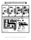
ASPF Model Insulation Kit
1830 DPIH36-42
3137 / 4260 DPIH48-61
Table 8
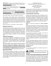
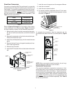
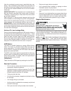
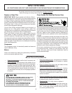
The following describes converting to “Horizontal Left-Hand”.
Conversion MUST be performed in an area that allows ac-
cess to all sides prior to placing the air handler in its final
location (See Figure 6).
PRIMARY
DRAIN
SECONDARY
DRAIN
DPIH KIT
Figure 6
1. Remove the (3) air handler access panels.
2. Remove the “J” shaped bracket that retains the evapo-
rator coil.
3. Remove the flowrator from the lower left side access
panel and slide out the evaporator coil and horizontal
drain pan.
4. Remove the gasket from the horizontal pan drain con-
nections.
5. Remove the oval shaped plastic plug from the left side
access panel. Remove the oval shaped rubber gasket
seal from the lower right side access panel.
6. The drain connections for the horizontal pan are sealed
with a thin coating of plastic. Carefully knock out this
plastic seal with a screwdriver and hammer. Note: The
upper drain will become the secondary drain which
is mandatory in many municipalities .
7. Install the plastic plug removed in step 5 to the right
side lower access panel and the oval shaped rubber
gasket to the lower left access panel.
8. Reinstall the evaporator coil with the horizontal panel
on the left side. Note: Push the assembly completely to
the rear to ensure the engagement of the upflow pan
with the rear channel bracket.
9. Install the “J” bracket (removed in step 2) to support the
upflow pan to the tie channel.
10. Attach all panels and the metering device.
Condensate Removal
The coil drain pan has a primary and a secondary drain with
3/4" NPT female connections. The connectors required are
3/4" NPT male, either PVC or metal pipe, and should be hand
tightened to a torque of approximately 37 in-lbs. to prevent
damage to the drain pan connection. An insertion depth be-
tween .355 to .485 inches (3-5 turns) should be expected at
this torque. Use the female (3/4 NPT) threaded fitting that
protrudes outside of the enclosure for external connections.
1. Ensure drain pan hole is NOT obstructed.
2. To prevent potential sweating and dripping on to finished
space, it may be necessary to insulate the condensate
drain line located inside the building. Use Armaflex® or
similar material.
A Secondary Condensate Drain Connection has been pro-
vided for areas where the building codes require it. Pitch the
drain line 1/4" per foot to provide free drainage. Insulate drain
lines located inside the building to prevent sweating. Install a
condensate trap to ensure proper drainage. If the secondary
drain line is required, run the line separately from the primary
drain and end it where it can be easily seen.
NOTE: Water coming from this line means the coil primary
drain is plugged and needs clearing.
CAUTION
If secondary drain is not installed, the secondary
access must be plugged.
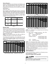
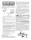
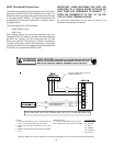
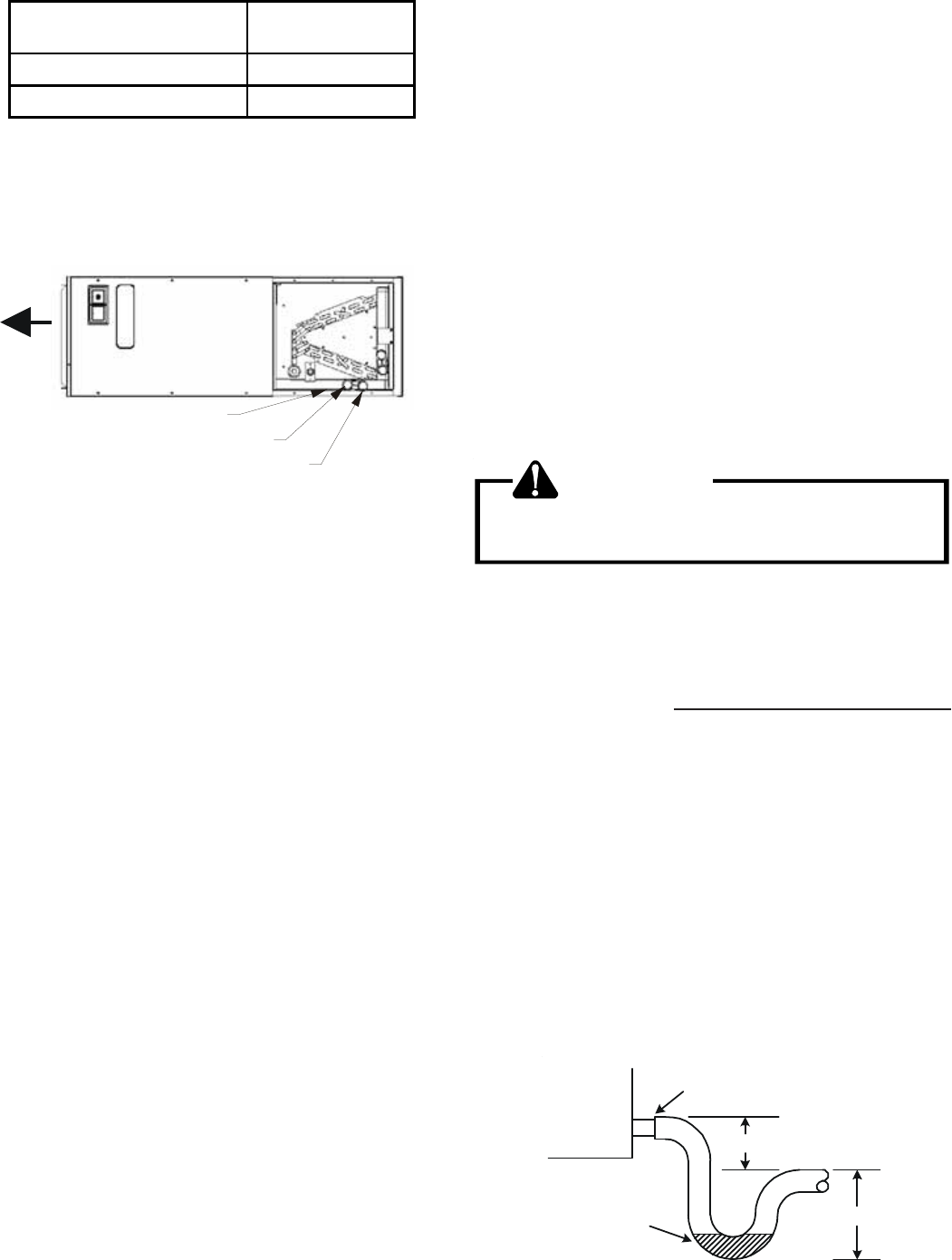
The installation must include a “P” style trap that is located
as close as is practical to the evaporator coil. See Figure 7
for details of a typical condensate line “P” trap.
NOTE: Trapped lines are required by many local codes. In
the absence of any prevailing local codes, please refer to the
requirements listed in the Uniform Mechanical Building Code.
A drain trap in a draw-through application prevents air from
being drawn back through the drain line during fan operation
thus preventing condensate from draining, and if connected
to a sewer line to prevent sewer gases from being drawn into
the airstream during blower operation.
Field experience has shown condensate drain traps with an
open vertical Tee between the air handler and the conden-
sate drain trap can improve condensate drainage in some
applications, but may cause excessive air discharge out of
the open Tee. Goodman® does not prohibit this type of drain
but we also do not recommend it due to the resulting air leak-
age. Regardless of the condensate drain design used, it is
the installer’s responsibility to ensure the condensate drain
system is of sufficient design to ensure proper condensate
removal from the coil drain pan.
Air Handler
3" MIN.
POSITIVE LIQUID
SEAL REQUIRED
AT TRAP
Drain
Connection
2" MIN.
Figure 7