


10
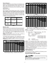
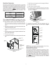
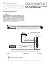
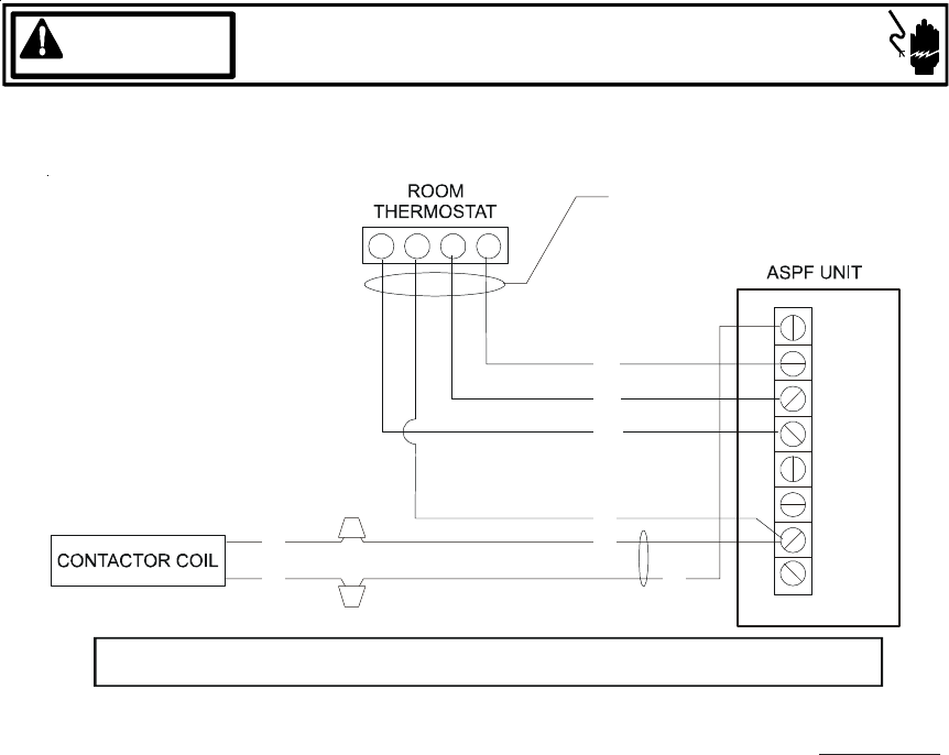
ASPF Thermostat Connections
NOTES:
1) OUTDOOR THERMOSTAT (OT-1) SHOULD BE THE
FIRST TO CLOSE AND THE LAST TO OPEN.
2) JUMPER W1 AND W2 TOGETHER IF OT-2 IS NOT
USED.
3) REMOVE WIRE WHEN USING OUTDOOR THERMO-
STAT.
NOMENCLATURE:
OT - OUTDOOR THERMOSTAT (OPTIONAL)
EHR - EMERGENCY HEAT RELAY (OPTIONAL)
COLOR CODES
RD - RED
YL - YELLOW
BL - BLUE
BR - BROWN
OR - ORANGE
WH - WHITE
Wiring is subject to change. Always refer to the wiring diagram on the unit for the most up-to-date wiring.
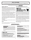
HIGH VOLTAGE!
DISCONNECT ALL POWER BEFORE SERVICING.
MULTIPLE POWER SOURCES MAY BE PRESENT. FAILURE TO DO SO
MAY CAUSE PROPERTY DAMAGE, PERSONAL INJURY OR DEATH.
WARNING
COOLING UNIT WITH OPTIONAL HEAT KITS OF 10 kW AND BELOW
GR
C
W1
YW
W2
Y2
Y1
O
G
R
TB
YL
BL
TO CONDENSING UNIT
24V CONNECTION
BL
YL
YL
WH
GR
RD
#18 GA. 4 WIRES WITH COOLING
3 WIRES WITHOUT
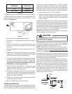
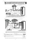
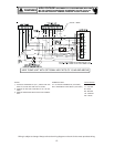
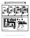
The following composite wiring diagrams detail various con-
figurations in which the ASPF air handlers can be used. Ex-
amples include single-stage cooling and heat pump with single
or two-stage electric heating. All these configurations can
be applied with convenient connections to outdoor thermo-
stat applications.
The following sections will be detailed:
• Single-Stage Cooling
• Heat Pump
Each diagram details the connections between room ther-
mostat and ASPF air handlers, and the connections between
the ASPF air handlers and the Condensing Unit (or Heat
Pump) with optional connections to Outdoor Thermostats.
For each configuration, refer to the explanation of the proper
jumper(s) to remove for the corresponding blower speed that
will result in the programmed EEM™ motor.
IMPORTANT: WHEN MATCHING THE ASPF AIR
HANDLERS TO A SINGLE SPEED COOLING OR
HEAT PUMP UNIT, REMEMBER TO CONNECT “Y”
FROM THE THERMOSTAT TO THE “Y2” ON THE
LOW VOLTAGE TERMINAL BOARD.
An equivalent thermostat can be used in place of the
Goodman thermostat part number.