


6
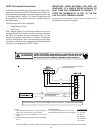
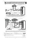
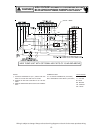
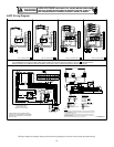
Low Voltage Connections
Several combinations of low voltage schemes are available,
depending on the presence of a heat kit and whether the
heat kit is single-stage or multi-staging. The low voltage con-
nections are determined by whether the outdoor unit is a con-
denser or heat pump. The 24V-control voltage connects the
air handler to the room thermostat and condenser. Low volt-
age wiring is to be copper conductors. A minimum of 18AWG
must be used for installations up to 50’ and 16AWG for in-
stallations over 50’. Low voltage wiring can be connected
through the top of the cabinet or either side. See the “Ther-
mostat Wiring” section of this manual for typical low voltage
wiring connections.
Refrigerant Lines
This product is factory-shipped under pressure. Follow
these instructions to prevent injury.
A quenching cloth is strongly recommended to prevent
scorching or marring of the equipment finish when
welding close to the painted surfaces. Use brazing
alloy of 5% minimum silver content.
Tubing Preparation
All cut ends are to be round, burr free, and clean.
Failure to follow this practice increases the chances for
refrigerant leaks. The suction line is spun closed and
requires pipe cutters to remove the closed end.
Post Brazing
Quench all welded joints with water or a wet rag.
Piping Size
For the correct tubing size, follow the specification
for the condenser/heat pump.
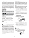
Applying too much heat to any tube can melt the tube. Torch
heat required to braze tubes of various sizes must be
proportional to the size of the tube. Service personnel must
use the appropriate heat level for the size of the tube being
brazed.
CAUTION
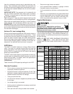
Special Instructions
This coil comes equipped with a check style flowrator for re-
frigerant management. For most installations with matching
applications, no change to the flowrator piston is required.
However, in mix-matched applications, a flowrator piston
change may be required. See the Goodman
®
piston kit chart
or consult your local distributor for details regarding mix-
matched piston sizing. If the mix-match application requires
a different piston size, change the piston in the flowrator on
the indoor coil before installing the coil and follow the proce-
dure shown below.
IMPORTANT NOTE: Torch heat required to braze tubes of
various sizes is proportional to the size of the tube. Tubes of
smaller size require less heat to bring the tube to brazing
temperature before adding brazing alloy. Applying too much
heat to any tube can melt the tube. Service personnel must
use the appropriate heat level for the size of the tube being
brazed.
NOTE: The use of a heat shield when brazing is recommended
to avoid burning the serial plate or the finish on the unit. Heat
trap or wet rags should be used to protect heat sensitive
components such as service valves and TXV valves.
1. Loosen the 13/16 nut 1 TURN ONLY to allow high pres-
sure tracer gas to escape. No gas indicates a possible
leak.
2. After the gas has escaped, remove the nut and discard
the black or brass cap.
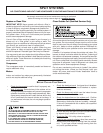
3. Remove the check piston to verify it is correct and then
replace the piston. See piston kit chart in instructions.
4. Use a tube cutter to remove the spin closure on the
suction line.
5. Remove the tailpiece clamped to the exterior and slide
the 13/16 nut into place.
6. Braze tailpiece to the line set liquid tube.
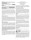
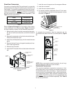
WHITE
TEFLON SEAL
PISTON
TAILPIECE
13/16” NUT
PLASTIC or BRASS CAP
Figure 1
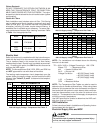
7. Insert the suction line into the connection, slide the in-
sulation and the rubber grommet at least 18" away from
the braze joint. Braze suction line.
8. AFTER THE TAILPIECE HAS COOLED, confirm posi-
tion of the white Teflon
®
seal and hand tighten the 13/16
nut.
9. Torque the 13/16 nut to 7-25 ft-lbs. or tighten 1/6 turn.
Excessive torque can cause orifices to stick. Use the
proper torque settings when tightening orifices.
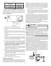
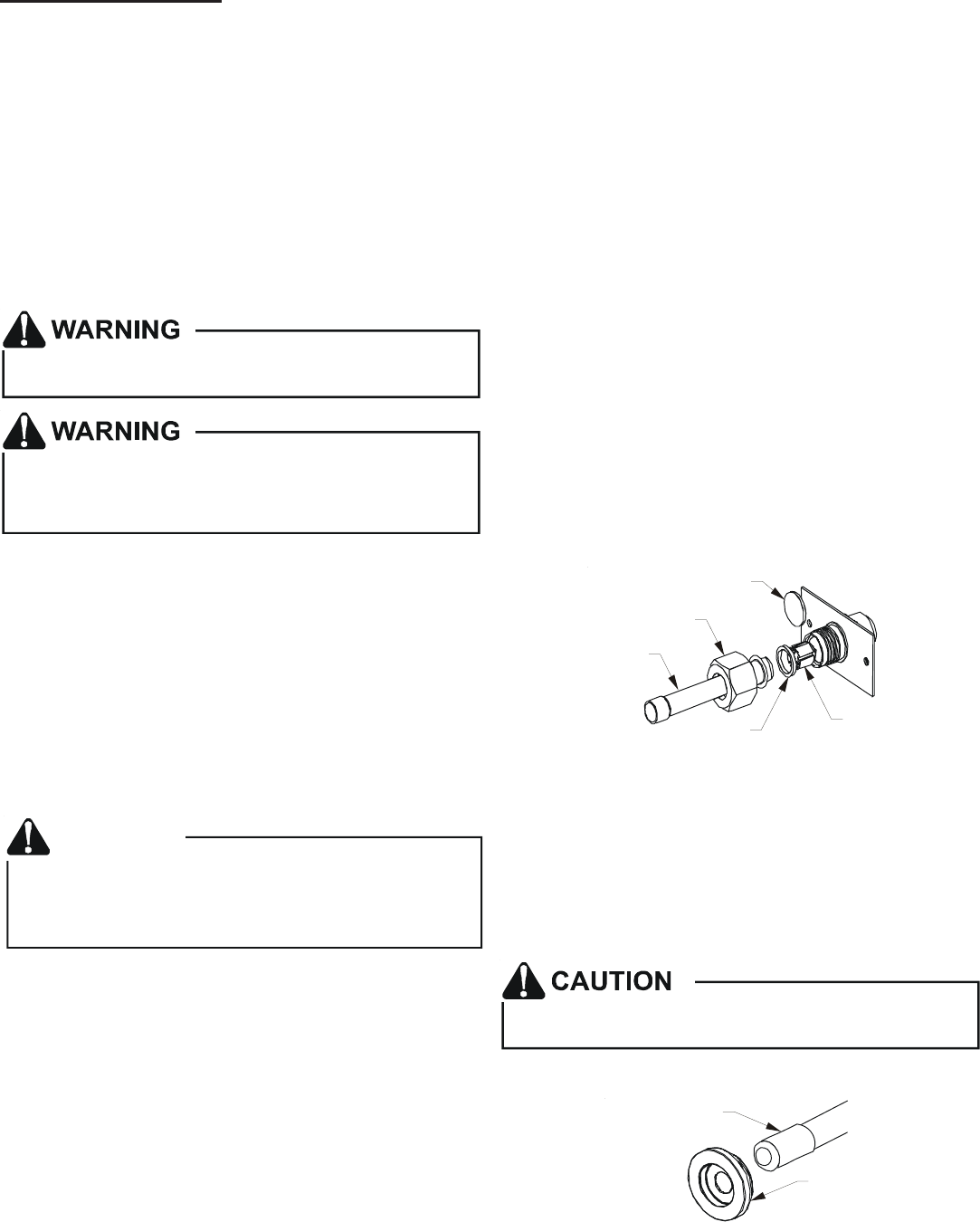
10. Replace suction line grommet and insulation.
RUBBER
GROMMET
SUCTION LINE
WITH SPIN CLOSURE
Figure 2