


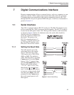

8.2 Calibration Procedure
Calibration requires four-wire 10 kΩ and 100 kΩ resistors of 25 ppm uncer
-
tainty and a 0Ω resistor (or short). For verification, 4 kΩ and40kΩ resistors of
25 ppm uncertainty, and a 1 MΩ resistor of 75 ppm uncertainty are also re
-
quired. The resistors are connected to the input the same way probes are. The
calibration procedure is as follows:
1.
Connect a 0Ω resistor to the input and measure its resistance. Note the
average error in the measurement. Adjust the CAL0 parameter by sub
-
tracting the measured error. For example, if the input is exactly 0.0Ω and
readout shows –0.11Ω, the CAL0 parameter should be adjusted by add
-
ing 0.11 to it.
2.
Connect a 10 kΩ resistor to the input and measure its resistance. Note
the average error in the measurement. Adjust the CAL10 parameter by
subtracting the measured error. For example, if the input is exactly
10.000 kΩ and the readout shows 10001.9Ω, the CAL100 parameter
should be adjusted by subtracting 1.9 from it.
3.
Connect a 100 kΩ resistor to the input and measure its resistance. Note
the average error in the measurement. Adjust the CAL100 parameter by
subtracting the measured error. For example, if the input is exactly
100.000 kΩ and the readout shows 999991Ω, the CAL400 parameter
should be adjusted by adding 9.0 to it.
4.
Verify the accuracy at 0Ω, 4 kΩ, 10 kΩ, 40 kΩ, 100 kΩ, and 1 MΩ. The
accuracy should be within the short-term accuracy limits given in the
specifications.
1504 Thermometer Readout
User’s Guide
36