


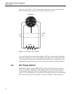
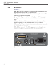
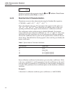

5.2 Rear Panel
See Figure 4.
Serial Port - The DB-9 connector is for interfacing the thermometer to a com
-
puter or terminal with serial RS-232 communications.
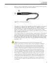
Probe Connector - At the rear of the thermometer is the probe connector. The
probe must be connected for operation.
Power Switch - The power switch is located on the rear of the thermometer.
The AC power switch turns the unit on and off. It does not control the DC
power.
AC Power - At the rear of the instrument is the removable power cord that
plugs into a standard 115 VAC grounded socket. (230 VAC optional)
DC Power - The DC power, located on the rear of the thermometer, powers the
unit immediately when connected.
IEEE-488 Port (optional) - The GPIB connector is for interfacing the ther-
mometer to a computer or terminal with IEEE-488 communications.
1504 Thermometer Readout
User’s Guide
16
RS-232
IEEE-488
PROBE
POWER
12V 1.0 A
–
+
l
201811
FLUKE HART SCIENTIFIC
www.hartscientific.com
115VAC 50/60 Hz 10W
NO USER SERVICABLE PARTS
Figure 4 1504 Back Panel