


4 Quick Start
This section briefly explains the basics of setting up and operating your 1504
thermometer readout.
4.1 Unpacking
Unpack the thermometer carefully and inspect it for any damage that may have
occurred during shipment. If there is shipping damage, notify the carrier
immediately.
Verify that the following components are present:
•
1504 Thermometer
•
Extra Probe Connector
•
Power Cord
• Manual
• Probe (optional—must be purchased separately)
• Battery Pack (optional—must be purchased separately)
4.2 Power
Your 1504 is configured for either 115 VAC (±10%) operation or 230 VAC
(±10%) operation. Be careful to only connect the 1504 to a mains supply of the
correct voltage. Otherwise, the instrument may be damaged. The required volt-
age is indicated on the back of the 1504. Power requirements are listed in Sec-
tion 3.1, Specifications. The IEC type power cord connects to the back of the
1504. The cord must be plugged in to a grounded outlet. The power switch is
located at the back of the 1504. The instrument can also be powered with a DC
battery option (see Section 4.4, DC Power Option).
When the 1504 is powered on, wait briefly while it initializes. It will then begin
measuring and displaying temperature.
Because of the quality of the components used in the 1504, it exhibits nearly
negligible drift as it warms up. The warm-up drift is typically less than 5 ppm.
Nevertheless, to ensure the best accuracy and stability, you may want to allow
the 1504 to warm up for ten minutes before use.
Accurate measurement requires that the probe be connected properly to the in
-
put and the correct probe characterization set.
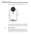
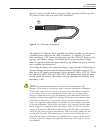
4.3 Connecting the Probe
The thermistor or RTD probe connects to the back of the 1504 using a five-pin
DIN plug. Figure 1 shows how a four-wire probe is wired to the five-pin DIN
connector. One pair of wires attaches to pins 1 and 2 and the other pair attaches
11
4 Quick Start
Unpacking