


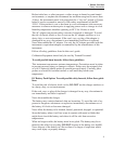

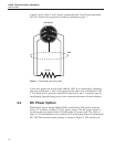
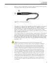

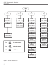

to pins 4 and 5. (Pins 1 and 5 source current and pins 2 and 4 sense the poten
-
tial.) If a shield wire is present it should be connected to pin 3.
A two-wire probe can also be used with the 1504. It is connected by attaching
one wire to both pins 1 and 2 of the plug and the other wire to both pins 4 and
5. If a shield wire is present it should be connected to pin 3. Accuracy may be
significantly degraded using a two-wire connection because of lead resistance.
4.4 DC Power Option
With the DC power option (Model 2502) installed the 1504 can be powered
from a 12 V battery or other 12 V DC power source. The DC power socket is
located on the rear panel of the 1504 above the AC power jack. The 1504 ac
-
cepts a 7/32 inch diameter, two-conductor DC power plug such as Switchcraft®
PN. 760. Observe the correct polarity as shown in Figure 2. The outside con
-
1504 Thermometer Readout
User’s Guide
12
1
2
4
5
RTD Sensor
Probe Connector
3
Shield
Figure 1 Connecting a four-wire probe