


Operator Manual
748223-K
June 2002
Rosemount Analytical Inc. A Division of Emerson Process Management Contents iii
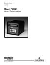
Model 7003M
7-0 REPLACEMENT PARTS......................................................................................................7-1
7-1 Circuit Board Replacement Policy.........................................................................................7-1
7-2 Matrix.....................................................................................................................................7-1
7-3 Replacement Parts - Model 7003M.......................................................................................7-2
7-4 Replacement Parts - Sensors................................................................................................7-3
a. Rechargeable Sensors ...................................................................................................7-3
b. Disposable Sensors ........................................................................................................7-4
8-0 RETURN OF MATERIAL......................................................................................................8-1
8-1 Return Of Material .................................................................................................................8-1
8-2 Customer Service ..................................................................................................................8-1
8-3 Training..................................................................................................................................8-1
LIST OF ILLUSTRATIONS
Figure 2-1. Sensor Ordering Matrix.......................................................................................... 2-2
Figure 2-2. Model 7003M Rear Panel Connections................................................................. 2-3
Figure 2-3. Power Jumpers and Fuses.................................................................................... 2-5
Figure 2-4. Current Output Connections.................................................................................. 2-7
Figure 3-1. Model 7003M Front Panel Controls and Indicators ............................................... 3-1
Figure 3-2. Model 7003M Operation Flow Diagram................................................................. 3-2
Figure 3-3. SETUP Mode Flowchart ...................................................................................... 3-12
Figure 3-4. Security Access Routine Flowchart..................................................................... 3-14
Figure 3-5. ALARM Mode Flowchart...................................................................................... 3-17
Figure 3-6. Action of Alarm Relay ON and OFF Setpoints .................................................... 3-19
Figure 4-1. CALIBRATION Mode and PRESSURE COMPENSATION Flowchart.................. 4-3
Figure 4-2. HOLD and DIAGNOSTICS Modes Flowchart ....................................................... 4-7