


Operator Manual
748223-K
June 2002
2-4 Installation Rosemount Analytical Inc. A Division of Emerson Process Management
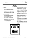
Model 7003M
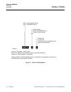
a. Sensor Cable
The sensor cable used with the Model
7003M may be of any length up to a
maximum of 1000 feet (305 m). (See
Table 2-1 below.)
The signal cable should be routed through
a conduit (customer-supplied) in
permanent installations or in cases where
the sensor is located more than a few feet
from the control unit. (See Table 2-2
below.)
NOTE:
In humid environments, temperature
changes can cause moisture to con-
dense in the conduit, resulting in sig-
nal noise and corrosion. To minimize
the effect of condensation, put desic-
cant (available locally) inside the con-
duit before sealing it.
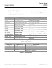
CABLE PART
NUMBER
LENGTH
191748 10 Feet (3.1 m)
193265-
SPECL
Any specified length
up to 1000 Feet (305
m)
Table 2-1. Sensor Cables
If conduit used:
1/2 inch NPT female connection on
bottom of control unit. (Conduit cus-
tomer-supplied.
If no conduit used:
Use cable connector assembly (PN
856831) to provide watertight seal. As-
sembly includes: Aluminum inner seal-
ing grommet for connector compression
nut.
Table 2-2. Analyzer Cable
Connections
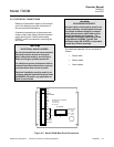
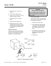
Connect Sensor Cable
1. Ensure that power is disconnected
and remove rear cover.
2. Install the conduit or cable clamp in
the left opening in the bottom rear of
the case.
3. Install the sensor cable in the
instrument through the cable clamp
and tighten the nut on the plug to
create a seal around the cable.
4. Refer to Figure 2-2 on page 2-3.
Using a flat-blade screwdriver,
connect the wires of the sensor cable
to the TB2-1, TB2-2, TB2-5 and TB2-
6 on the rear panel of the analyzer.
5. Replace the rear cover if no other
connections are to be made. Do not
overtighten the cover retaining screws
to avoid stripping the threads in the
plastic case.
b. Power Connections
Electrical power is supplied to the
analyzer via a customer-supplied three
conductor cable, type SJT, minimum 18
AWG. Refer to the installation drawing in
the rear of this manual.
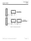
Jumpers and Fuses
To verify the jumper location for the
specified power (115 or 230 VAC) or if the
analyzer is to be connected to a different
power source, refer to Figure 2-3 on page
2-5and set jumpers and fuse as follows:
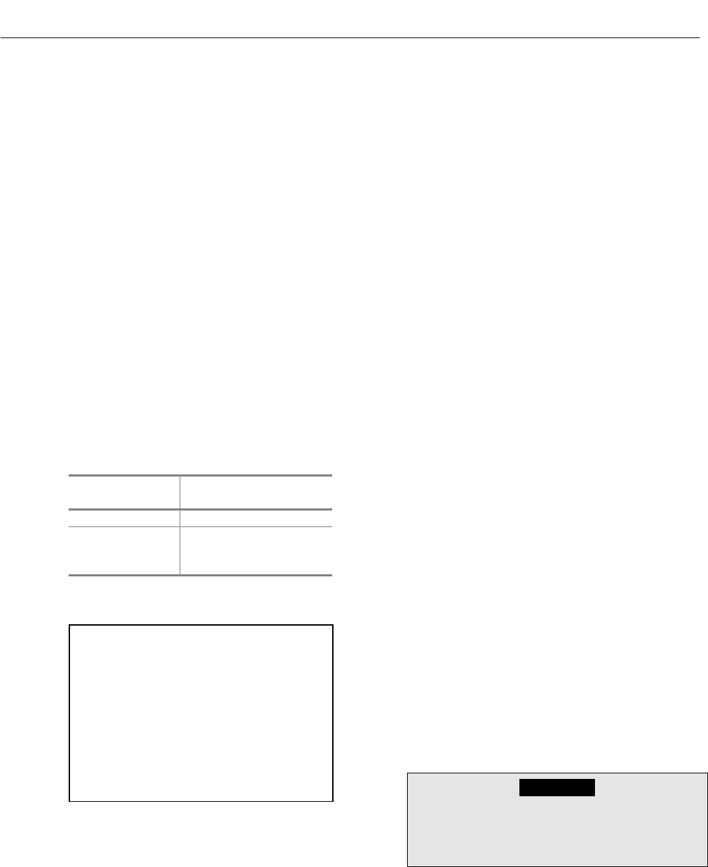
WARNING
ELECTRICAL SHOCK HAZARD
Disconnect power to analyzer before con-
tinuing.