


Operator Manual
748223-K
June 2002
2-8 Installation Rosemount Analytical Inc. A Division of Emerson Process Management
Model 7003M
2-6 RELAY CONTACTS FOR ALARMS OR
ON/OFF-CONTROLS
NOTE:
Whenever "Alarm" is used, it refers to
either alarm or ON/OFF Control, de-
pending on how the relays are con-
nected and configured by the
customer.
Ratings
Two sets of alarm relay contacts are
provided for actuation of customer-
supplied alarm and/or ON/OFF-Control
functions. (see Section 1-6 specifications
on page 1-4).
Power Failure
Removal of AC power from the analyzer,
as in a power failure, removes power from
both relay coils. The Model 7003M
should operate on a different AC power
source than the Alarm relay contacts.
Radio Frequency Interference (RFI)
If alarm contacts are connected to any
device that causes radio frequency
interference (RFI), an arc suppressor (PN
858728) should be used to minimize RFI.
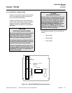
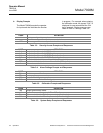
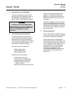
Connecting Devices to Relay Contacts
WARNING
RELAY CONTACTS
Relay contacts wired to separate power
source must be disconnected before
servicing.
Connect alarm or ON/OFF-Control
devices to the relay contacts as follows:
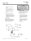
1. Disconnect power; remove rear cover
of analyzer.
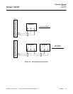
2. Connect leads from the external
alarm or ON/OFF Control system
(see Figure 2-2 on page 2-3).
TB3-1 Alarm 1Com
TB3-2 Alarm 1NC
TB3-3 Alarm 1NO
TB3-4 Alarm 2Com
TB3-5 Alarm 2NC
TB3-6 Alarm 2NO
3. Connect other end of output cable to
terminals of alarm device.
4. Replace the rear cover. Do not
overtighten cover retaining screws, to
avoid stripping the threads in the
plastic case.
NOTE:
For installation in a Class I, Division 2
location, refer to the Specifications in
the Preface section, and the approval
label on the analyzer for Factory Mu-
tual limitations on contact ratings.