


support.dell.com Service Information for Technicians 7-23
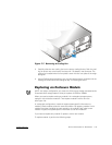
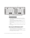
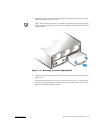
11. To install the replacement backplane board, place the board between the chassis
halves.
Ensure that the board is right-side up and the dual-bus split backplane connector
faces the back half of the chassis while the hard-disk drive connectors face the
front half.
NOTE: The PowerVault 200S and 201S only accept an eight–hard-disk drive back-
plane; the PowerVault 210S and 211S only accept a 12–hard-disk drive backplane.
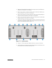
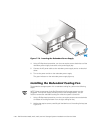
12. Using an 11 1/2-inch–long Allen, 5/64-inch ball driver, thread two screws through
the left module bay, through the screw holes in the backplane board, and into the
screw holes of the front half of the chassis.
Turn the screws until they catch in the screw holes of the front half of the chas-
sis. Do not tighten the screws at this time. Install the two screws in the right
module bay in the same manner.
NOTE: A magnetized ball driver makes it easier to install the screws in the mod-
ule bays.
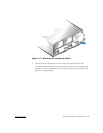
13. Thread the 11 remaining screws through the inside of the component area of the
back chassis half, through the screw holes in the backplane board, and into the
screw holes of the front half of the chassis. Turn the screws until they catch in
the screw holes of the front half of the chassis. Do not tighten the screws at this
time.
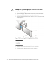
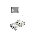
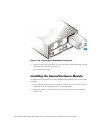
14. Carefully insert the left module (module A) into the left module bay.
Push the module all the way to the back of the bay and at the same time adjust
the backplane board so the board connector aligns with the module connector.
Push the module until it is seated in the board connector.
NOTE: Temporarily installing the modules and seating their connectors to the
connectors on the backplane board ensures that the backplane board will be
aligned when you screw the two chassis halves together.
15. Using a Phillips-head screwdriver, tighten the screw to secure the module to the
chassis.
16. Repeat steps 14 and 15 for the right (second) module or terminator blank.
17. Tighten the 11 screws on the inside of the component area to secure the chassis
front, backplane board, and chassis back together.
18. Using a Phillips-head screwdriver, loosen the captive screws at the top of the
modules.
19. Remove both modules.
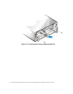
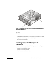
20. Using an 11 1/2-inch–long Allen, 5/64-inch ball driver, tighten the two screws in
the left module (module A) bay (see Figure 7-12) and then tighten two screws in
the right module (module B) bay.