


support.dell.com Service Information for Technicians 7-9
6\VWHP0HVVDJHV
System messages alert you to a possible operating problem or to a conflict between
the software and hardware. If you receive a system message, see the HP OpenView
NNM SE x.x and Dell OpenManage HIP x.x documentation for suggestions on resolv-
ing any problems indicated by the message.
3DUWV5HSODFHPHQW3URFHGXUHV
This section provides information about the following procedures for removing and
replacing components and assemblies in the storage system:
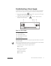
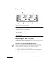
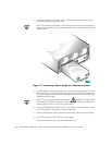
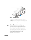
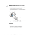
Replacing the Power Supply
Replacing a Cooling Fan
Replacing an Enclosure Module
Removing and Reinstalling the Component Mounting Bracket
Removing the Dual-Bus Split Backplane Module
Removing the SCSI Backplane Board
Removing and Reinstalling the Lock Bar
Unless otherwise noted, each procedure assumes the following conditions:
You have performed the steps in "Precautionary Measures," found earlier in this
chapter.
You can replace or reinstall a part by performing the removal procedure in reverse
order, unless additional information is provided.
5HFRPPHQGHG7RROV
Most of the procedures in this appendix require the use of one or more of the follow-
ing tools:
Number 1 and number 2 Phillips-head screwdrivers
11 1/2-inch–long Allen, 5/64-inch ball driver (magnetized)
Wrist grounding strap, as explained in "Precautionary Measures," found earlier in
this chapter
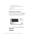
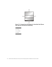
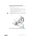
&RPSXWHU 2ULHQ WDWLRQ
When performing the procedures in this section, refer to the locations or directions
relative to the storage system as shown in Figure 7-3, unless otherwise specified.