


DR
®
TRIMMER/MOWER
™
Safety & Operating Instructions 17
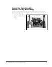
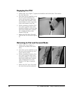
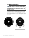
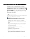
Figure 9
Your Machine’s Cutting Cords
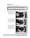
The following figures (Figures 9 and 10) illustrate how the cords are installed on the line
plates. These figures show the line plates from a cross section point of view. It may look
complicated, but once you’ve done it a couple of times, it’s easy. There are two sets of
installation points on each line plate, 180 degrees apart. One set of holes is for larger cord
(155 mil) and is marked with large arrows. The other set of holes accommodates smaller cord
(130 mil) and is marked with small arrows. Always install two cords opposite each other for
the best performance.
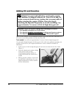
WARNING! Always turn the engine off when installing or changing
cutting cords.
Important!
Running the trimmer with only one cord installed, or cords
installed at other than 180 degrees can cause excessive vibration and
may damage the machine.
Figure 10