


Braun Corporation FMVSS No. 403 Quick Reference Installation Sheet 31312
s
i
s
s
a
h
C
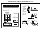
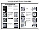
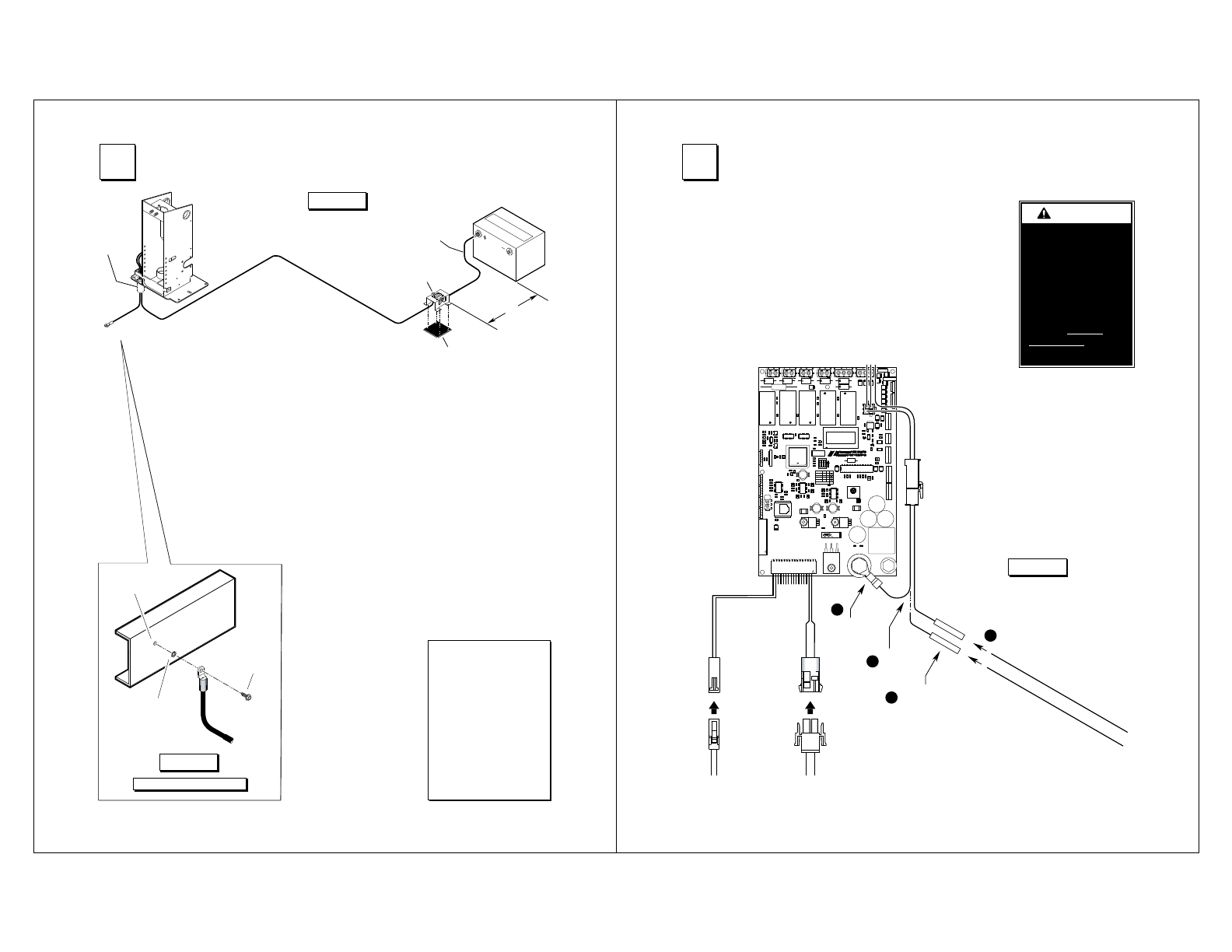
1. Drill 1-1/8” diameter grom-
met access hole. Check
under the vehicle for
obstructions.
2. Insert grommet. Secure
grommet with two self-tap
screws.
e
l
b
a
C
r
e
w
o
P
.
x
u
A
.
t
a
B
.
so
P
.
g
e
N
"
4
x
"
4
x
"
8
/
1
c
i
ts
a
l
P
"
2
1
.
xa
M
t
i
u
c
ri
C
y
r
t
n
e
S
d
a
e
L
el
b
a
C
t
e
m
mo
r
G
d
n
u
or
G
e
l
b
a
C
e
m
a
r
F
eb
uT
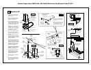
3. Route ground and power
cables through grommet.
Route cables clear of
exhaust, other hot areas
and moving parts.
4. Connect ground cable to
vehicle framing member
(see detail below).
5.
Attach power cable to
Auxiliary terminal of
Circuit Sentr
y. Attach one
end of 18" lead cable to
the Battery Circuit Sentry
terminal.
5/16"
External Tooth
Star
Washer
9/32" Diameter
Pilot Hole
Thread Cutting
Screw
&IGURE/
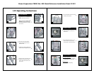
Locate Circuit Sentry within
12" of positive (+) battery
terminal. Mount Circuit
Sentry with four self-tap
screws. Sandwich 1/8"
x 4" x 4" plastic between
Circuit Sentry and mount
-
ing surface.
6. Carefully connect opposite
end of lead cable to Posi-
tive (+) post of battery.
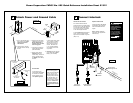
Ground Cable Mounting
&IGURE.
Ground Cable
Lift mounted ground
cable ground cable must
be mounted to a vehicle
framing member to pro
-
vide optimum ground.
3
!TTACH0OWERAND'ROUND#ABLE
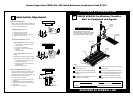
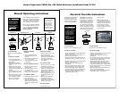
Vehicle and Lift Interlock
A 2-circuit lift/vehicle interlock
interface harness is provided inside
the tower cove
r. The Grey/Red wire
is connected to the battery power
stud. A butt connector is provided
on the
Yellow/Light Blue wire.
To meet minimum NHTSA require-
ments, connect vehicle interlock
signal wires as detailed in Figure
P
(Steps 1-4):
Optional Interlock Kits
Universal Interlock Kit 30940K
is available for easy interface
with vehicle OEM electronic
signals.
Note: Detailed installation
instructions are supplied with
interlock kit(s).
R/YG
UB .TL/Y
KB
NB
W
K
B
Cut
wire.
Install butt
connecto
r.
Threshold
Warning
Sensor Harness
Door Cut-Out
Switch Harness
Connect vehicle
interlock signal wires.
Disconnect
and discard.
R
/
Y
G
)
l
a
n
g
i
S
e
r
u
c
e
S
e
l
c
i
h
e
V
(
)
l
a
n
g
i
S
d
e
w
o
t
S
t
f
i
L
(
U
B
.
T
L
/
Y
KB
Y
G
F1
R17
+
C7
+
U11
+
C1
C53
R64
U8
W9
J8
4
3
2
R73
1
J5
29
18
7
R43
R32
1
21W
R28
2
1
D14
C19
C17
R37
1
W20
R5
R63
1
K5
1
U7
R20
R59
C54
D12
D1
Q6
C43
Q4
R65
C52
C37
R53
R67
C23
R1
R9
C4
3
W10
2
1
W8
R22
2
1
R54
R70
R19
D32
C45
C29
R10
Q3
R25
R49
D8
C21
C18
D2
R71
D15
R14
K3
D9
C36
R38
R6
D18
D16
C38
R72
31W
D19
Q7
21
J6
C15
W6
2
1
Y1
01C
D27
C35
C25
R66
C33
D4
7R
+
R18
C31
D10
R13
C51
06R
D24
C20
C34
L3
C39
D28
C26
C9
D22
C8
C24
R15
D3
R35
C32
C41
K2
R50
C30
1
R47
R57
R4
D23
R46
40
+
R42
R12
R39
D7
C42
K6
C28
R24
D6
U3
D5
C27
J9
D29
R68
R55
R34
C14
R29
R44
R33
C6
R27
R40
R45
R11
C13
R2
R41
R31
5W
Q2
R69
R51
R8
R48
Q1
W16
3
W11
D30
2
1
R58
R16
R21
R30
K1
321
ON
ON
ON
S1
+
+
C46
D21
R26
11
C
R3
K4
C5
C12
U10
D26
D17
7 6 5
4
3
2
D13
U9
+
1
71W
C16
Q5
R56
D11
C47
C22
W7
D31
+
C40
2
1
+
C3
+
R36
R52
R23
D20
U5
1
41W
+
100024-001
ESDHAZARD
CAUTION!
REVISION
MED-LO
LOW
SPEED
ON
OFFON
ON
OFFON
OFFOFF
1 2
ENABLE
ON
TRIFOLD
3
ON
BUZZER
12V
GND
GND
12V
12V
MED-HI
HIGH
1
U
21U
+
C2
+
C50
4W
3W
1
W
1
2W
U4
L2
L1
J4
COUNTER
BARRIER
LIFT
K
C
O
LR
ET
N
I
rosn
eS
dl
o
h
ser
hT
t
imiL
dlofn
U
timi
L
dloF
timi
L
nwoD
timi
L
r
e
i
rraB
t
i
miL
yol
peD
ti
mi
L
wotS
ti
m
iL ro
ol
F
ti
miL
p
U
timiL rooD
J2
U6
23
1
2
3
1
2
3
1
2
3
1
2
3
4
5
J1
J1
J3
1
3
4
2
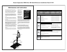
&IGURE0
W
A
RNING
Install and verify
proper operation of
all NHTS
A mandated
interlocks as
specified. Failure
to do so will result
in a non-compliant
installation and may
result in serious
bodily injury and/or
property damage.
4
#ONNECT)NTERLOCK
Ground Cable Corrosion:
When mounting ground
cables, remove undercoat
-
ing, dirt, rust, etc. from
framing member around
mounting holes (minimum
5/8” diameter area).
Ap-
ply protective coating to
mounting holes to prevent
corrosion. Failure to do
so will void warranty of
certain electrical compo
-
nents.