


Braun Corporation FMVSS No. 403 Quick Reference Installation Sheet 31312
e
c
a
r
B
g
n
i
t
n
u
o
M
l
a
c
i
t
r
e
V
e
m
a
r
F
e
b
u
T
2
3ECURE,IFT
e
g
d
e
W
e
t
a
l
P
e
g
d
e
W
e
t
a
l
P
r
o
o
l
F
e
m
a
r
F
e
b
u
T
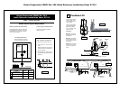
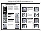
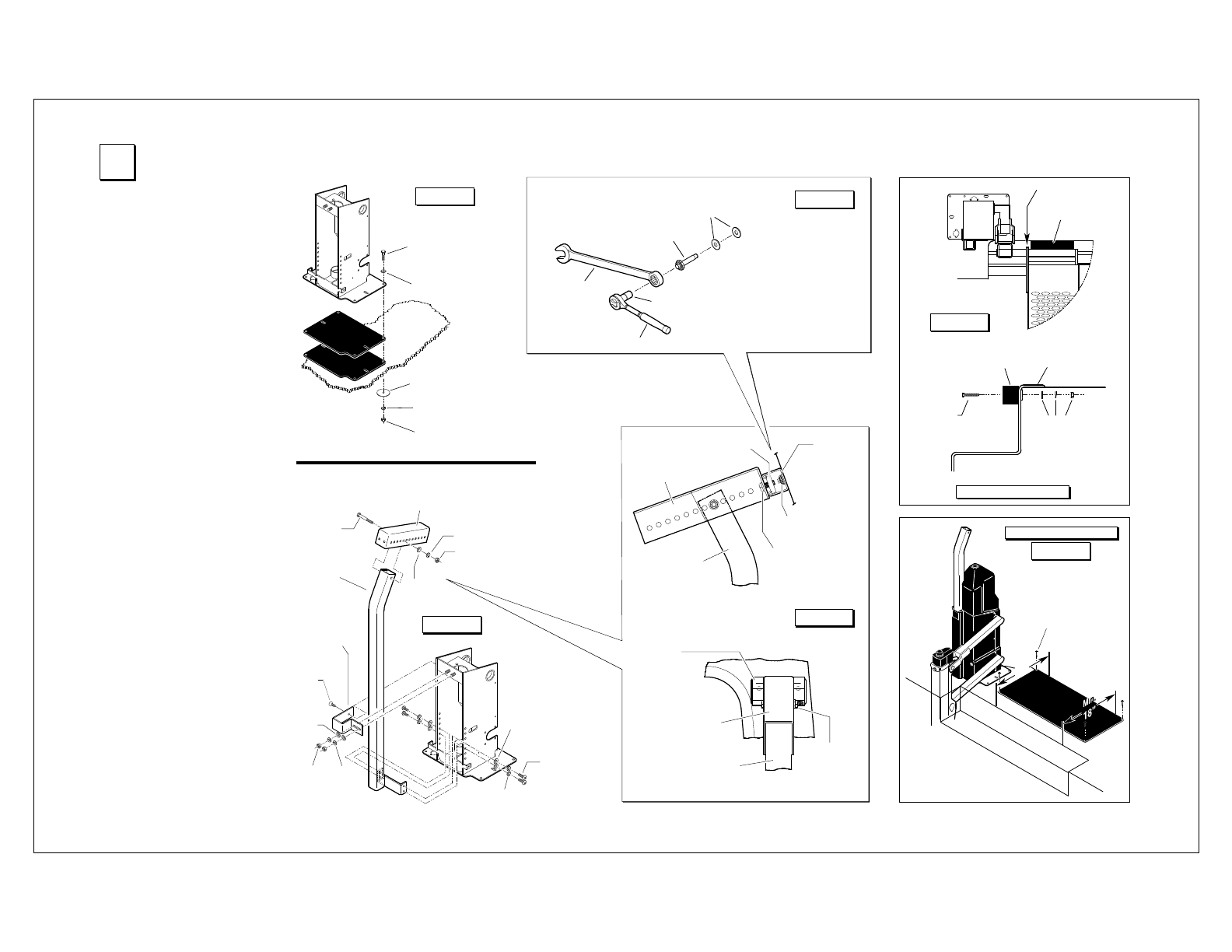
3/8-16 Hex Bolt
(Minimum 4)
• One in each corner.
• Lengths as required
per application.
5/16" Flat
Washer
3/8" Body Washer
3/8" Lock Washer
3/8-16 Hex Nut
Hardware
Typical
All Positions
Position
wedges
as needed.
&IGURE(
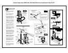
Docking
Bumper
Outer Pivot
Platform
Docking
Bumper
Stepwell
Floor
Trim
5/16" Flat
Washer
3/8" Lock
Washer
3/8-16 Hex Nut
3/8-16 x 2"
Hex Bolt
(Qty: 2)
Docking Bumper
r
o
o
l
F
d
e
h
s
i
n
i
F
f
o
e
g
d
E
d
l
o
h
s
e
r
h
T
g
n
i
n
r
a
W
.
n
i
M
"
8
1
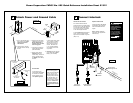
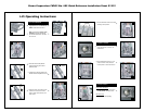
#10-16 x 1-1/2"
Wafer Head Phillips
Self-Drilling Screw
(Qty: 4)
Threshold Warning
Upper
Adjustment
Bracket
Upper
Mounting
Channel
3/8-16 x 1"
Hex Cap Screw
with
Lock
Washer
(Qty: 2)
3/8-16 Slide Nut
Vertical
Mounting
Brace
Fab-Lock Bolt
Upper
Mounting
Channel
Upper
Adjustment
Bracket
Vertical
Mounting
Brace
3/8-16 x 3"
Hex Bolt
with
Lock
Washer
and Hex Nut
Wall (C Pillar)
5/16-18 x 7/8"
Button Head
Cap Screw
Upper
Mounting
Bracket
5/16"
Hex
Nut
5/16-18 x 3/4"
Flat Head
Screw
3/8-16 x 3"
Hex Bolt
Upper
Adjustment
Bracket
3/8" Lock
Washer
3/8" Hex
Nut
5/16" Flat
Washer
5/16"
Lock
Washer
&IGURE)
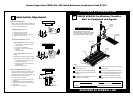
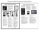
5/16" Flat
Washer
5/16"
Flat
Washer
5/16" Lock
Washer
Vertical
Mounting
Brace
Fab-Lock Bolt
1/4" Flat
Washers
Ratchet Wrench
5/16" Socket
5/8" Wrench
1. Remove rubber
washer and install
1/4" flat washers.
3. Place a 5/8"
wrench onto
bolt head and
secure tightly
4. Place a 5/16" socket onto the inner
screw and tighten (turn clockwise).
5.
Turn socket until Fab-Lock has
expanded against metal surface.
Fab-Lock Bolt Installation
&IGURE*
&IGU
RE+
&IGU
RE-
&IGU
RE,
2. Insert Fab-Lock bolts (minimum
2) fully through mounting channel
and C pilla
r.
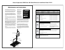
Note: Cut bracket o
ff flush with
mounting brace and install foam
padded cover using cable ties.
1. Temporarily secure base plate by
installing sheet metal screws in
base plate slots.
2. Secure vertical mounting brace
and upper mounting bracket to
frame tube. See Figure I.
3.
Temporarily assemble upper ad
-
justment bracket and upper mount
-
ing channel. See Figure K. Posi-
tion assembly and mark mounting
holes on van wall (C pillar).
Carefully drill 5/16" diameter wall
mounting holes. Secure upper
mounting channel to wall (C pillar)
using expanding Fab-Lock bolts
(minimum 2). See Figure J.
4. Secure upper adjustment bracket
and upper mounting channel as-
sembly to vertical mounting brace.
5. Carefully operate lift through all
functions checking for clearances
(specified in Figures D-I).
Adjust
lift position and/or upper mounting
hardware as needed.
6. Drill 3/8" diameter holes through
floor using the corner holes in the
base plate as a template. Refer to
Figure H. Insert 3/8"-16 hex bolts
and secure below
floor as speci-
fied in Figure H (bolt lengths as
required per application).
Tighten all mounting hardware
securely.
All fasteners must meet
FMVSS 571.403 Section 6.3.
7. Cut upper adjustment bracket off
flush with mounting brace and
install foam padded cover using
cable ties. Note: Cover power
unit before cutting bracket.
8. Position and secure docking bum
-
per. See Figure L.
9. Position and secure warning sen
-
sor mat as specified in Figure M.
Connect wiring harness to lift as
shown in Figure
P.
Hardware
typical
opposite side