


Installation 14
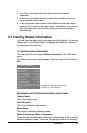
2.4 Signal connection
a) Connection of video signals
The connected equipment must comply to all relevant safety
demands.
Important: The use of low-quality video cables can distort the video
signal and influence diagnosis.
1. Check the impedance of the imaging board that produces the
video signals you want to connect. It must be 50 or 75 Ohm (just
like the input of the display). If not, the quality of the images on the
display will be inferior.
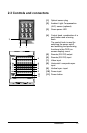
2. Connect the video output of the computers imaging board to the
video and sync inputs on the displays rear panel. Use a proper
video cable. The video cable is not supplied with the display,
unless the display comes as part of a complete BARCO MeDis
system, that also contains an imaging board.
The inputs accept the following signals:
Video with separate horizontal and vertical sync.
- The video cable has 3 wires.
- Connect the video signal to the connector Video {7}.
- Connect the horizontal sync signal to the connector HS/CS {8}.
- Connect the vertical sync signal to the connector VS {9}.
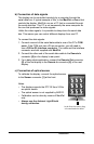
Video with external composite sync.
- The video cable has 2 wires.
- Connect the video signal to the connector Video {7}.
- Connect the composite sync signal to the connector HS/CS {8}.
Video with internal composite sync (sync on video).
- The video cable has 1 wire.
- Connect the video (with sync) signal to the connector Video {7}.
- The vertical sync pulse must be at least 2 lines long.
Notes:
The video inputs cannot be connected in loop-through (daisy-
chain).
The required video amplitude: 700 mV.
The required sync. amplitude: 500 mV.
!