DIGITAL INPUT/OUTPUT CARD IOD-144 USER MANUAL
3-1
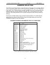
OPTION SELECTION
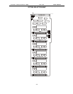
Refer to the illustrated setup programs on the diskette provided with the card when
reading this section of the manual. Also, refer to the OPTION SELECTION MAP on the
following page.
Base address selection is covered both by the diskette and in the next section of this
manual.
Interrupts are accepted on the I/O connector, pin 9 (port C3). The interrupt signal is
positive true. Interrupts are unconditionally enabled if the IEN jumper is installed, or
enabled by program if the INP jumper is installed and I/O connector pin 1 (port C) is low.
Interrupts are disabled if (a) neither the IEN or INP jumper is installed, or (b) if the INP
jumper is installed but I/O connector pin 1 (port C7) is held high. User interrupts are
directed to interrupts #2 through #7, #10 through #12, #14 and #15 by jumpers installed
at locations labeled IRQ2 through IRQ15.
The foregoing are the only manual setups necessary to use the IOD-144. Input/Output
selection is done, via software, by writing to the PPI 8255-5 Control Registers as
described in the PROGRAMMING section of this manual.
IOD-144 provides a means to enable/disable the tristate I/O buffers under program
control. If the BEN/TST jumper on the card is installed in the BEN position, the I/O
buffers are permanently enabled. However, if the jumper is placed in the TST position,
enable/disable of the buffers is possible under software control via the Control Register
as described in the Software Programming section of this manual.


