


DIGITAL INPUT/OUTPUT CARD IOD-144 USER MANUAL
6-4
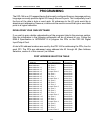
PROGRAMMING EXAMPLE
The following programming example is provided as a guide to assist you in developing
your working software. In this example, the card base address is 2D0 hex and I/O
lines of Port 0 are to be setup as follows:
port A = Input
port B =Output
port C hi = Input
port C lo =Output
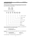
Configure bits of the Control Register as:
D7 D6 D5 D4 D3 D2 D1 D0
1 0 0 1 1 0 0 0
| | | | | | | |
| | | | | | | |____ Port C Lo = output
| | | | | | I
| | | | | | |_________ Port B = output
| | | | I I
| | | | | |______________ Mode 0
| | | | |
| | | | |___________________ Port C Hi = input
| | | |
| | | |________________________ Port A = input
| | |
| | |_____________________________ Mode 0
| |
| |__________________________________ Mode 0
|
|_______________________________________ Active Mode Set
This corresponds to 98 hex. If the card base address is 2D0 hex, use the BASIC OUT
command to write to the control register as follows:
10 BASEADDR=&H2D0
20 OUT BASEADDR+3,&H98
To read the inputs at Port A and the upper nybble of Port C, use the BASIC INPUT
command:
30 X=INP(BASEADDR) 'Read Port A
40 Y=INP(BASEADDR+2)/16 'Read Port C Hi
To set outputs high ("1") at Port B and the lower nybble of Port C: