


DIGITAL INPUT/OUTPUT CARD IOD-144 USER MANUAL
2-2
IOD-144 to termination panels such as ACCES model STA-50. Also, this provides
compatibility with OPTO-22, Gordos, Potter & Brumfield, etc. module mounting racks.
Every second conductor of the flat cables is grounded to minimize the effect of crosstalk
between signals. If needed for external circuits +5VDC power is available on each I/O
connector pin 49. If you use this power, we recommend that you include a 1A fast blow
fuse in your circuits in order to avoid possible damage to the host computer.
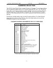
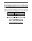
The board occupies 24 consecutive bytes within the I/O address space. The base
address is selectable via ADDRESS SETUP DIP switches (A5-A9) anywhere within the
hex 000-3FF range.
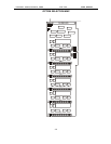
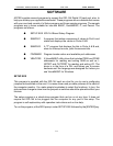
Utility software provided on diskette with the IOD-144 card is an illustrated setup
program. Interactive displays show locations and proper settings of DIP switches and
jumpers to set up board address, interrupt levels, and interrupt enable. Additionally, two
sample programs and a utility driver for use with VisualBASIC for Windows are
provided. See the Software section of this manual for a detailed description of the latter.
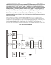
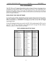
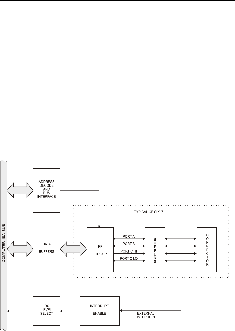
IOD-144 BLOCK DIAGRAM