


DIGITAL INPUT/OUTPUT CARD IOD-144 USER MANUAL
6-1
PROGRAMMING
The IOD-144 is an I/O mapped device that is easily configured from any language and any
language can easily perform digital I/O through the card's ports. This is especially true if
the form of the data is byte or word wide. All references to the I/O ports would be in
absolute port addressing. However, a table could be used to convert the byte or word data
ports to a logical reference.
DEVELOPING YOUR OWN SOFTWARE
If you wish to gain a better understanding of the programs listed in the previous section,
then the information in the following paragraphs will be of interest to you. Follow the
8255-5 Specification in APPENDIX A to program the PPIs on the IOD-144 Digital
Input/Output Card.
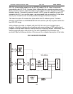
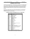
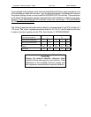
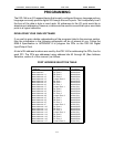
A total of 24 address locations are used by the IOD-144 for addressing the PPIs; four for
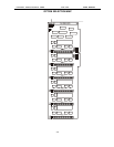
each PPI. The PPIs are addressed using address bits A3 through A0 (See Address
Selection, section 4 of this manual.) as follows:
PORT ADDRESS SELECTION TABLE
Address Port Assignment Operation
Base Address
Base Address +1
Base Address +2
Base Address +3
Base Address +4
Base Address +5
Base Address +6
Base Address +7
Base Address +8
Base Address +9
Base Address +A
Base Address +B
Base Address +C
Base Address +D
Base Address +E
Base Address +F
Base Address +10
Base Address +11
Base Address +12
Base Address +13
Base Address +14
Base Address +15
Base Address +16
Base Address +17
PA Port 0
PB Port 0
PC Port 0
Control Port 0
PA Port 1
PB Port 1
PC Port 1
Control Port 1
PA Port 2
PB Port 2
PC Port 2
Control Port 2
PA Port 3
PB Port 3
PC Port 3
Control Port 3
PA Port 4
PB Port 4
PC Port 4
Control Port 4
PA Port 5
PB Port 5
PC Port 5
Control Port 5
Read/Write
Read/Write
Read/Write
Write Only
Read/Write
Read/Write
Read/Write
Write Only
Read/Write
Read/Write
Read/Write
Write Only
Read/Write
Read/Write
Read/Write
Write Only
Read/Write
Read/Write
Read/Write
Write Only
Read/Write
Read/Write
Read/Write
Write Only