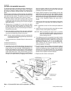
DUCT COVERS - Units are shipped with all air duct
openings covered.
For
side duct applications;
1.Remove and discard the supply and return air duct
covers.
2.Connect ductwork to duct flanges on the rear of the
unit.
For
bottom duct applications;
1. Remove the side supply air duct cover to gain
access to the bottom supply air knockout panel.
2. Remove and discard the bottom knockout panel.
3. Replace the side duct cover.
4. With filter section access panel removed from the
unit, remove and discard the bottom return air
knockout panel.
5. Replace the filter access panel.
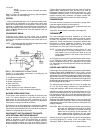
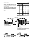
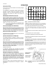
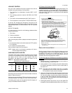
FIG. 6
- DIMENSIONS & CLEARANCES - 3, 4 & 5 TONS
CLEARANCES
HOLE
KNOCKOUT
SIZE
(DIA.)
USED FOR
A7/8" *
Control Wiring
(Side or Bottom)**
B2" *
Power Wiring
(Side or Bottom)
*Knockouts in the bottom of the unit can be located
by the slice in the insulation.
**
Do not remove the 2" knockout ring.
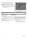
FILTER ACCESS
ELECTRIC
HEAT
ACCESS
B - POWER WIRING ENTRY
A, B
WIRING ENTRY
(See Detail “B”)
OUTDOOR
COIL
A - CONTROL WIRING ENTRY
3
⁄
4
“ PVC FEMALE
COND. DRAIN
(See Detail ”A")
BOTTOM SUPPLY &
RETURN AIR OPENINGS
(SEE NOTE)
32
5
⁄
8
17
1
⁄
2
11
1
⁄
2
7
7
⁄
8
6
3
⁄
4
8
1
⁄
8
8
3
⁄
8
17
1
⁄
2
6
1
⁄
2
5
3
⁄
8
2
1
⁄
2
82
1
⁄
4
44
7
⁄
8
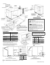
(Direct-Drive Units)
FIELD-SUPPLIED
DISCONNECT SWITCH
LOCATION
BLOWER
ACCESS
CONTROL
BOX ACCESS
Shown separately to illustrate bottom
duct openings and power connection
locations.
NOTE: For curb-mounted units, refer to the duct
hanger dimensions of the curb for the proper size
of the supply and return air duct connections.
COMPRESSOR
ACCESS
UNIT BASE WITH RAILS
11
1
⁄
2
4
5
⁄
8
3
7
7
⁄
8
6
1
⁄
2
17
1
⁄
2
11
1
⁄
2
17
1
⁄
2
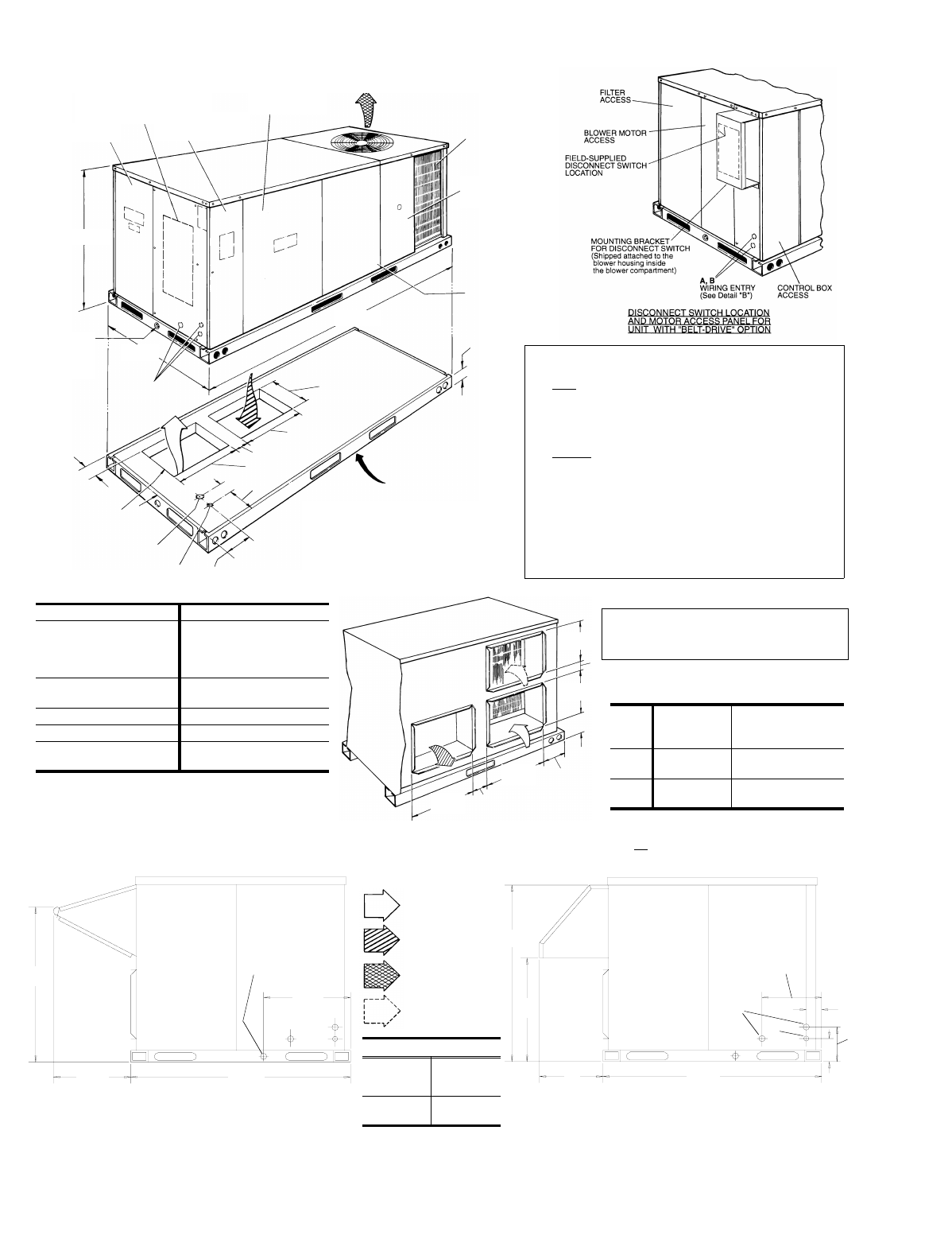
UNIT WITH ECONOMIZER RAIN HOOD
REAR VIEW
SIDE SUPPLY AND RETURN
AIR OPENINGS
FRONT VIEW
UTILITIES ENTRY DATA
All dimensions are in inches. They are sub-
ject to change without notice. Certified di-
mensions will be provided upon request.
44
7
⁄
8
B
30
7
⁄
8
"A"
10
1
⁄
4
4
3
⁄
8
A
3
1
⁄
2
8
1
⁄
4
19
1
⁄
8
44
7
⁄
8
19
1
⁄
2
27
1
⁄
2
19
3
⁄
4
3
⁄
4
“ CONDENSATE
DRAIN
(must be trapped)
DETAIL “A”
DETAIL “B”
UNIT WITH FIXED OUTDOOR
AIR/MOTORIZED DAMPER RAIN HOOD
DIMENSION "A"
FIXED
OUTDOOR
AIR DAMPER
12
MOTORIZED
DAMPER
16
1
⁄
2
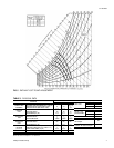
AIR FLOW LEGEND
RETURN AIR
SUPPLY AIR
OUTDOOR AIR
OUTDOOR AIR
(Economizer)
Front 24"
Back
12" (Less Economizer)
36" (With Economizer or
Fixed Air/Motorized
Damper)
Left Side
(Filter Access)
24" (Less Economizer)
36" (With Economizer)
Right Side (OD Coil) 24"
Below Unit
1
20"
Above Unit
2
72" (For Outdoor Air
Discharge)
NOTE:
Units and ductwork are approved for zero clearance to combustible
materials when equipped with electric heaters.
1
Units may be installed on combustible floors made from wood or
class A, B or C roof covering material. (Applicable in USA only).
2
Units must be installed oudoors. Overhanging structures or shrubs
should not obstruct the outdoor coil nor the fan outlet.
511.06-N5Y
8 Unitary Products Group