These units must be installed in accordance with the current
edition of the following national and local safety codes:
In U.S.A.:
1. National Electrical Code ANSI/NFPA No. 70.
2. Local electric utility requirements.
In Canada:
1. Canadian Electrical Code C22.1
2. Canadian Installation Codes CAN/CGA-B149.1 and .2.
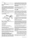
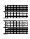
Refer to Table 1 for Unit Application Data.
If components are to be added to a unit to meet local codes, they
are to be installed at the dealer’s and / or the customer’s expense.
Size of unit for proposed installation should be based on heat
loss / heat gain calculation made according to the methods of
Air Conditioning Contractors of America (ACCA).
LOCATION
Use the following guidelines to select a suitable location for
these units.
1. Unit is designed for outdoor installation only.
2. Outdoor coil must have an unlimited supply of air.
3. For ground level installation, a level pad or slab should be
used. The thickness and size of the pad or slab used should
meet local codes and unit weight. Do not tie the slab to the
building foundation.
4. Roof structures must be able to support the weight of the unit
and its options and / or accessories. Unit must be installed on
a solid level roof curb or appropriate angle iron frame.
CAUTION: If a unit is to be installed on a roof curb or special frame
other than a YORK roof curb, gasketing must be applied to
all surfaces that come in contact with the unit underside.
5. Maintain level tolerance to 1/2" maximum across the entire
length or width of the unit.
6. Elevate the unit sufficiently to prevent any blockage of the
air entrances by snow in areas where there will be snow
accumulation. Check the local weather bureau for the ex-
pected snow accumulation in your area.
OUTDOOR COIL CONDENSATE DRAINAGE PRECAUTION
Condensate will drain from the outdoor coil during the heating
and defrost cycles. Normally this condensate may be allowed
to drain directly onto the ground/roof. A gravel bed is
recommended to prevent mud splashing.
WARNING: The unit should not be installed in an area where mud
or ice could cause personal injury. Remember that
condensate will drip from the outdoor coil during heat
and defrost cycles and that this condensate will freeze
when the temperature of the outdoor air is below 32
°
F.
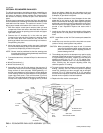
RIGGING AND HANDLING
Exercise care when moving the unit. Do not remove any
packaging until the unit is near the place of installation. Rig the
unit by attaching chain or cable slings to the lifting holes
provided in the base rails. Spreaders, whose length exceeds
the largest dimension across the unit, MUST be used across
the top of the unit.
BEFORE LIFTING A UNIT, MAKE SURE THAT ITS WEIGHT
IS DISTRIBUTED EQUALLY ON THE CABLES SO THAT IT
WILL LIFT EVENLY.
Units may also be moved or lifted with a forklift. Slotted
openings in the base rails are provided for this purpose.
LENGTH OF FORKS MUST BE A MINIMUM OF 42".
Remove the nesting brackets from the four corners on top of
the unit. All screws that are removed when taking these
brackets off must be replaced on the unit.
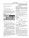
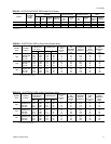
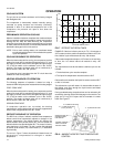
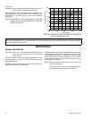
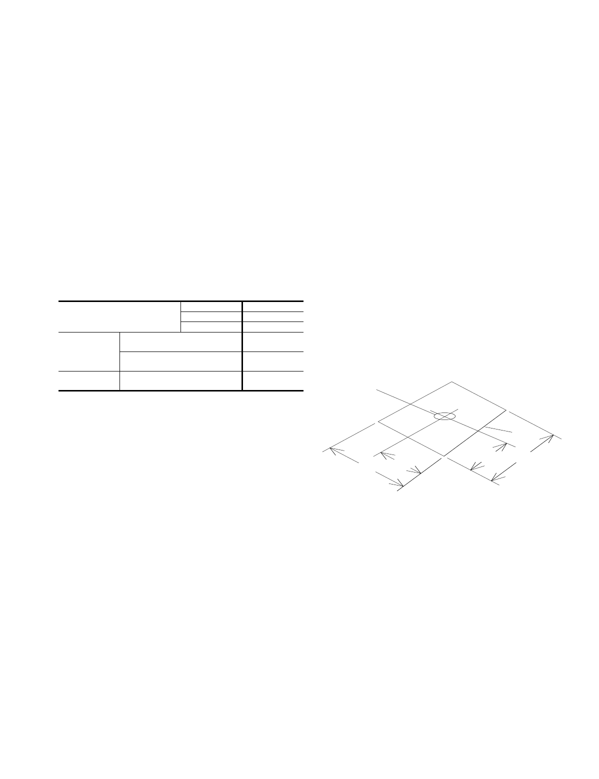
Refer to Table 3 for unit weights and to Figure 1 for approximate
center of gravity.
CLEARANCES
All units require certain clearances for proper operation and
service. Refer to Figure 6 for the clearances required for
combustible construction, servicing, and proper unit operation.
WARNING:Do not permit overhanging structures or shrubs to
obstruct outdoor air discharge outlet.
DUCTWORK
Ductwork should be designed and sized according to the
methods in Manual Q of the Air Conditioning Contractors of
America (ACCA).
A closed return duct system shall be used. This shall not
preclude use of economizers or outdoor fresh air intake. The
supply and return air duct connections at the unit should be
made with flexible joints to minimize the transmission of noise.
The supply and return air duct systems should be designed for
the CFM and static requirements of the job. They should NOT
be sized to match the dimensions of the duct connections on
the unit.
CAUTION: When fastening ductwork to the side duct flanges
on the unit, insert the screws through the duct
flanges only. DO NOT insert the screws through the
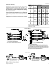
INSTALLATION
Voltage Variation
Min. / Max.*
208/230V 187 / 253
460V 414 / 506
575V 518 / 630
Cooling
Wet Bulb Temperature (
°
F) of Air
on Indoor Coil, Min. / Max.
57 / 72
Dry Bulb Temperature (
°
F) of Air
on Outdoor Coil, Min. / Max.
45 / 120
Heating
Minimum Dry Bulb Temperature
(
°
F) of Air on Outdoor Coil
-10
*Rated in accordance with ARI Standard 110, utilization range "A".
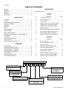
TABLE 1
- UNIT APPLICATION DATA
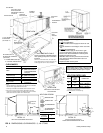
82
1
⁄
4
“
40
3
⁄
4
“
44
7
⁄
8
“
19
3
⁄
4
“
APPROXINATE
CENTER OF
GRAVITY
FRONT
FIG. 1
- CENTER OF GRAVITY
511.06-N5Y
Unitary Products Group 3