casing.
Outdoor ductwork must be insulated and water-
proofed.
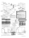
Refer to Figure 6 for information concerning side and bottom
supply and return air duct openings.
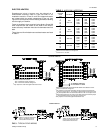
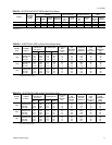
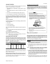
FILTERS
1" filters are supplied with each unit. 2" replacement filters may
be used with no modification to the filter racks. Filters must
always be installed ahead of the evaporator coil and must be
kept clean or replaced with same size and type. Dirty filters will
reduce the capacity of the unit and will result in frosted coils or
safety shutdown. Minimum filter area and required sizes are
shown in Table 3.
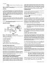
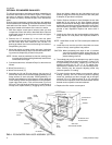
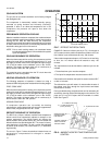
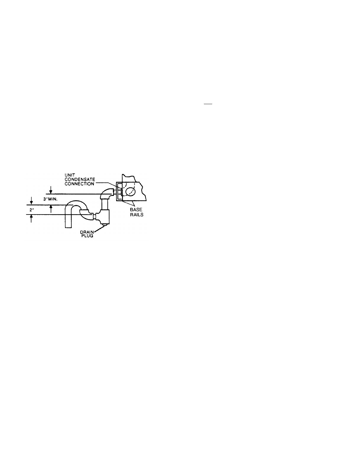
CONDENSATE DRAIN
Plumbing must conform to local codes. Use a sealing
compound on male pipe threads. Install a condensate drain line
from the 3/4" PVC female connection on the unit to spill into an
open drain.
NOTE: The condensate drain line MUST be trapped to provide
proper drainage. See Figure 2.
SERVICE ACCESS
Access to all serviceable components is provided by the
following removable panels:
•
Compressor compartment
•
Heater compartment
•
Blower compartment
•
Main control box
•
Filter compartment
•
Motor Access (on units w/belt-drive option)
Refer to Figure 6 for location of these access panels.
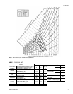
BLOWER SPEED SELECTION
Three blower motor speeds are available on the direct-drive
units. The speed selection for the direct-drive units is
determined by the CFM and ESP requirements of the
applications. All units with belt-drive option have an adjustable
motor pulley to achieve the above conditions.
All direct-drive units are shipped with the black wire (labeled
#8) connected to the high speed tap on the blower motor. If a
lower blower speed is desired, this wire should be moved to the
medium or low speed tap on the motor.
DISCONNECT SWITCH BRACKET FOR UNITS
WITH OPTIONAL BELT-DRIVE BRACKET
A special bracket for mounting a field-supplied disconnect
switch is provided in each unit ordered with an optional
belt-drive supply air blower. The bracket is shipped inside the
blower compartment taped to the top of the blower housing.
Install the bracket on the left hand side of the unit as shown in
Figure 6. Several existing screws at the top of the unit and one
approximately midway down from the top will be used for
mounting the bracket. Screws should be loosened only - NOT
REMOVED. Mounting holes in the bracket have elongated
keyways allowing easy installation. Re-tighten screws after
bracket is in place to ensure panels will remain leak tight.
COMPRESSORS
On some units the compressor is mounted on springs which
have been tightened down for shipment only.
After this unit is installed, back out the compressor bolts until
the sleeve clears the top grommet.
CAUTION: Do Not loosen compressor mounting bolts.
THERMOSTAT
The room thermostat should be located on an inside wall
approximately 56" above the floor where it will not be subject
to drafts, sun exposure, or heat from electrical fixtures or
appliances. Follow manufacturer’s instructions enclosed with
thermostat for general installation procedure. Color coded
insulated wires (#18 AWG) should be used to connect
thermostat to unit. See Figure 3 for wiring details.
NOTE: On units with economizer, remove jumper "J1" from
terminals 8 and 10 on plug connector J3/P7 on the
relay board in the unit control box. Refer to the unit
wiring labels located on the inside of the control box
access panel.
An "Emergency Heat" position is provided with the thermostat.
In the "Emergency Heat" position, the thermostat will allow
electric resistance heat only. The compressor will be locked
out. A pilot light on the thermostat will indicate that the switch
is on "EM HT".
POWER AND CONTROL WIRING
Field wiring to the unit must conform to provisions of the National
Electrical Code (NEC) ANSI/NFPA No. 70 (in U.S.A.), current
Canadian Electrical Code (CEC) C22.1 (in Canada) and/or local
ordinances. The unit must be electrically grounded in accordance
with the NEC and CEC (as specified above) and/or local codes.
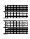
Voltage tolerances which must be maintained at the compressor
terminals during starting and running conditions are indicated on
the unit Rating Plate and Table 1.
The wiring harness furnished with this unit is an integral part
of a UL and C.G.A. design certified unit. Field alteration to
comply with electrical codes should not be required.
A disconnect switch should be field provided for the unit. The
switch must be separate from all other circuits. Refer to Figure
6 for installation location. If any of the wire supplied with the unit
must be replaced, replacement wire must be of the type shown
on the wiring diagram.
Electrical lines must be sized properly to carry the load. USE
COPPER CONDUCTORS ONLY. Each unit must be wired with
a separate branch circuit fed directly from the meter panel and
properly protected.
CAUTION: When connecting electrical power and control wir-
ing to the unit, waterproof type connectors MUST
BE USED so that water or moisture cannot be
drawn into the unit during normal operation. The
above waterproofing conditions will also apply
when installing a field-supplied disconnect switch.
Refer to Figure 3 for typical field wiring and to the appropriate
unit wiring diagram for control circuit and power wiring
information. Refer to Tables 9 and 10 for electrical data.
FIG. 2
- RECOMMENDED DRAIN PIPING
511.06-N5Y
4 Unitary Products Group