ELECTRIC HEATERS
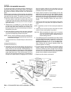
Supplemental electric heaters may be ordered as a
field-installed accessory. Refer to Form 530.18-N7.1V for
installation instruction. These UL and C.G.A. approved heaters
are located within the central compartment of the unit (see
Figure 6 for access panel) with the heating elements extending
into the supply air chamber.
Fuses are supplied, where required, by the factory. Some KW
sizes require fuses and others do not. Refer to the electric
heater accessory installation instruction for the heater electrical
data.
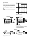
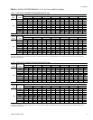
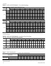
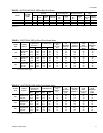
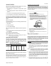
The minimum air flow limitations across these heaters are listed
in Table 2.
NOMINAL
HEATER
SIZE
KW
VOLTAGE
1
UNIT MODEL SIZE, NOMINAL TONS
345
MINIMUM SUPPLY AIR CFM
5
7
10
15
20
30
208 /
230-1-60
1,100
1,100
1,200
1,200
1,300
2
–
1,300
1,300
1,300
1,300
1,300
2
–
1,600
1,600
1,600
1,600
1,600
1,600
5
7
10
15
20
30
208 /
230-3-60
1,100
1,100
1,200
1,200
1,300
2
–
1,300
1,300
1,300
1,300
1,300
–
1,600
1,600
1,600
1,600
1,600
1,600
7
10
15
20
30
460-3-60
1,100
1,200
1,200
1,300
–
1,300
1,300
1,300
1,300
–
1,600
1,600
1,600
1,600
1,600
10
15
20
30
575-3-60
1,200
1,200
1,300
–
1,300
1,300
1,400
–
1,600
1,600
1,600
1,800
1208/230 and 460 volt heaters are UL approved.
208/230 and 575 volt heaters are CGA approved.
2
CGA minimum is 1,400 CFM.
TABLE 2
- AIR FLOW LIMITATIONS
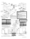
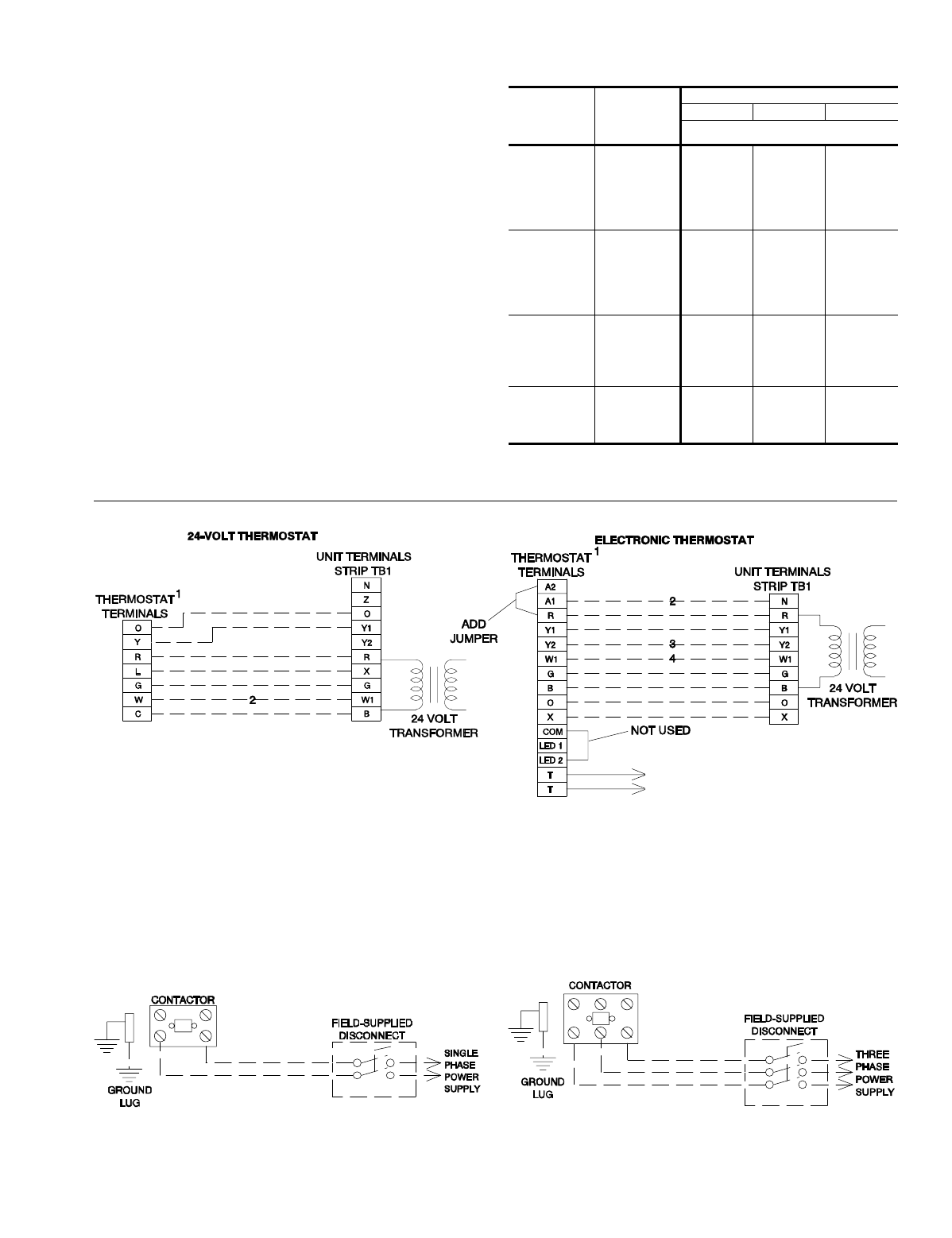
REFER TO ELECTRICAL DATA
TABLES TO SIZE THE DISCONNECT
SWITCH, THE WIRING AND THE
OVERCURRENT PROTECTION.
REFER TO ELECTRICAL DATA
TABLES TO SIZE THE DISCONNECT
SWITCH, THE WIRING AND THE
OVERCURRENT PROTECTION.
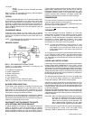
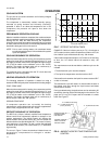
TO REMOTE SENSOR
2TH04702224 IF USED
FIG. 3
- TYPICAL FIELD WIRING
CONTROL WIRING
POWER WIRING
1
24-volt thermostat with subbase;
-2TH11704024 for manual changeover.
-2TH11704124 for automatic changeover.
2
Only required on units with supplemental electric heat.
1
Electronic progammable thermostat 2ET04700324 with subbase for either
manual or automatic changeover.
2
Only required on units with economizer. Remove jumper L2 from terminals
4 and 9 on jumper plug P7. The outdoor air intake dampers will return to their
fully closed position when the thermostat switches to the “unoccupied” mode.
3
Second stage cooling may be used on units with economizer. Remove jumper
J1 from terminals 8 and 10 on jumper plug connector P7.
4
Only required on units with supplemental electric heat.
511.06-N5Y
Unitary Products Group 5