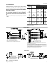
LOCKOUT CONTROL
Any one of four conditions will put the system into a lock-out
condition during the heating or cooling mode:
1.
The discharge line temperature reaches 255
°
F (215
°
F
reset) or,
2. The discharge pressure reaches 398 PSIG (310 PSIG
reset) or,
3.
The suction line freezestat equals 26
°
F (38
°
F reset) or,
4. The low-pressure cut-out equals 7 PSIG (22 PSIG reset).
A lock-out will energize the emergency heat light on the
thermostat and the red LED light on the unit relay board. Turning
the thermostat switch to "Off" then back to "On", will reset the
system.
NOTICE TO OWNER:
If a lockout occurs, check for the following problems before
calling a serviceman:
1. Dirty filters.
2. Snow accumulation.
3. Leaf or debris blockage.
After eliminating the problem, attempt to restart the system as
follows:
•
turn the system switch on the thermostat to its "OFF" position
for 10 seconds.
•
turn it back to its original position.
If the unit doesn’t start, call a serviceman.
NOTE: Models with an anti-recycle accessory will have a
5-minute delay before starting.
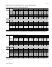
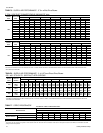
CHECKING SUPPLY AIR CFM
The speed of the supply air blower will depend on the required
CFM, the unit accessories and the static resistances of both
the supply and the return air duct systems. With this
information, the speed for the supply air blower can be
determined from the blower performance and static resistance
data on Tables 4 through 7.
Knowing the required blower RPM and the blower motor HP,
the speed setting for the supply air motor can be determined.
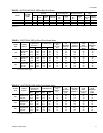
The setting (turns open) for the optional belt-drive supply air
pulley can be determined from Table 11.
OPTIONAL BELT-DRIVE BLOWER
All units with belt-drive blowers have single speed motors. The
variable pitch pulley on the blower motor can be adjusted to
obtain the desired supply air CFM. Refer to Table 8 for blower
motor drive data. The tension on the belts should be adjusted
as shown in Figure 9.
Start the supply air blower motor. Adjust the resistances in both
the supply and the return air duct systems to balance the air
distribution throughout the conditioned space. The job
specifications may require that this balancing be done by
someone other than the equipment installer.
To check the supply air CFM after the initial balancing has been
completed:
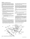
1.
Remove the (two)
5
⁄
16
" dot plugs from the holes located on
the filter access panel side of the unit.
2. Insert at least 8" of 1/4 inch tubing into each of these holes
for sufficient penetration into the air flow on both sides of
the indoor coil.
NOTE: The tubes must be inserted and held in a position
perpendicular to the air flow so that velocity pressure
will not affect the static pressure readings.
3. Using an inclined manometer, determine the pressure drop
across a dry indoor coil. Since the moisture on an indoor
coil may vary greatly, measuring the pressure drop across
a wet coil under field conditions would be inaccurate. To
ensure a dry coil, the compressors should be de-energized
while the test is being run.
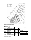
4. Knowing the pressure drop across a dry coil, the actual CFM
through the unit can be determined from the curve in Figure 10.
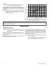
TURNS
OPEN*
BLOWER DRIVE RANGE (RPM)
3 TON 4 TON 5 TON
5
4
3
2
1
0
780
842
904
966
1028
1090
790
856
922
988
1054
1120
850
924
998
1072
1246
1220
*Pulley can be adjusted in half-turn increments.
TABLE 11
- BELT-DRIVE SUPPLY AIR
MOTOR PULLEY ADJUSTMENT
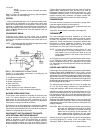
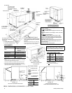
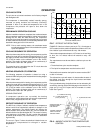
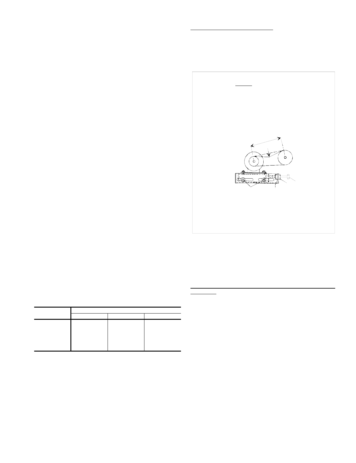
SPAN LENGTH
DEFL FORCE
* NEVER LOOSEN
(A)
(C)*
(D)
CAUTION
Procedure for adjusting belt tension:
1. Loosen nut (D) from the motor mount.
2. Never loosen nuts (C) from each other while loosening nut (D).
3. Adjust the tension by turning bolt (B).
4. Do not loosen the four nuts (top and bottom) (A); unless additional tensioning
distance is required; immediately re-tighten these bolts if loosened.
5. Use a belt tension checker to apply a perpendicular force to one belt at the
midpoint of the span as shown. The deflection force should be applied
until a specific deflection distance of 4mm (5/32")is obtained. To determine
the deflection distance from normal position, use a straight edge from
sheave to sheave as a reference line. The recommended deflection force
is as follows:
Tension new belts at the max. deflection force recommended for the belt
section. Check the belt tension at least two times during the first 24 hours of
operation. Any re-tensioning should fall between the min. and max.
deflection force values.
6. After adjusting, re-tighten nut (D) against the motor mount taking care not
to loosen nuts (C).
(B)
FIG. 9
- BELT ADJUSTMENT
511.06-N5Y
Unitary Products Group 13