• Pin 5 connected to ground (pin 4) places the amplifier in standby mode. Standby
mode turns off all output, although the amplier is still receiving power. Use the
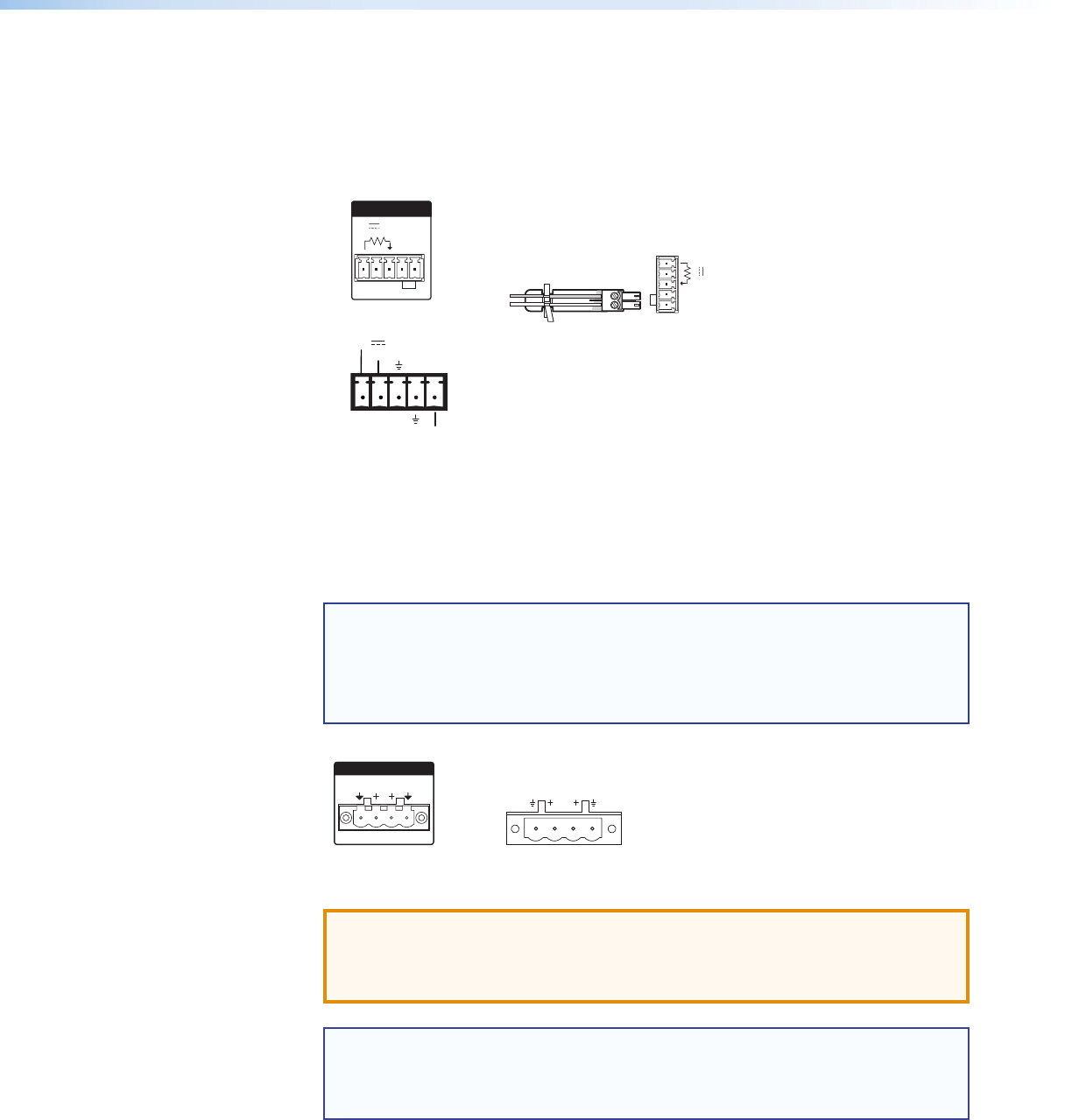
included 2-pin, 3.5 mm captive screw connector to remotely ground pin 5.
The power indicator LED lights amber when the amplier is in standby mode.
Remote Switching to Standby Mode
123 45
STANDBY
VOL/MUTE
10V 50 mA
STANDBY
G
V
10V
GC
REMOTE
50mA
STANDBY
G
V
GC
10V
50mA
or
å
Stereo audio output connector (channels 1 and 2) — Marked “1” and “2”
for the output channels, wire the included 4-pole, 5 mm screw lock captive screw
connector to output stereo audio. Observe the correct polarities for each channel.
See the following steps. The output is designed to power 4 or 8 ohm speakers and is
rated at 100 watts per channel at 4 ohms and 60 watts per channel at 8 ohms.
NOTES: • You must use Class 2 wiring for this output to comply with UL
requirements.
• The stereo audio output connector may be labeled one of two ways
(see the images below). The wiring and function are the same,
whichever way your product is labeled.
12
OUTPUT
XPA 1002
CLASS 2 WIRING
1
2
8Ω/4Ω OUTPUTS
or
ATTENTION: Failure to follow these instructions may result in damage to
the unit.
Do not tie channel outputs 1 and 2 to each other or to ground.
Doing so will short out the outputs and/or damage the amplifier.
NOTE: The output power of the XPA 1002 can be effectively doubled by using
only one input channel and bridging the output. The XPA 1002 will output
200 watts at 8 ohms in bridged mode. See “Bridged Mono Output” on
page 19 for wiring instructions when bridging the XPA 1002.
XTRA Series • Operation 14


