100-240V 1.3A
50-60Hz
Remove screws
(both sides) to release
IEC connector plate.
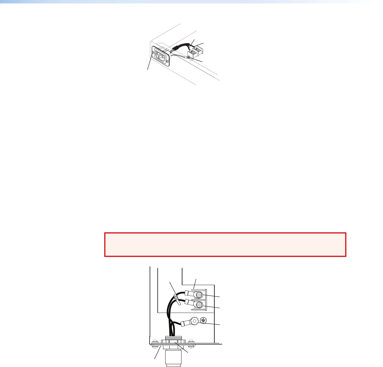
Remove nut
Blue Wire
Brown Wire
L
N
Figure 6. Removing the IEC Connector
4. Remove the ground wire nut from the grounding stud on the bottom of the
enclosure, as shown above.
5. Remove the 2 screws from the IEC plate, and remove the IEC connector plate and the
attached wires through the rear panel of the XPA, as shown above.
6. Thread the 18-gauge power wires through the length of the electrical conduit tube.
7. Install the EMT adapter plate with conduit attached into the opening from which the
IEC connector was removed in step 5.
8. Slide the conduit nut over the bundle of wires exiting the conduit and onto the
conduit itself. Hand tighten the conduit nut to the conduit.
9. Attach the EMT adapter plate assembly to the XPA using the 2 screws that were
removed in step 5.
10. Connect the black hot (line) and white neutral wires to the terminal block on the
PCB using the 2 screws that were removed in step 3. Use the included zip tie wrap to
secure the two wires together close to the terminals. See the following illustration.
WARNING: Failure to follow these instructions may result in serious injury.
Ensure that you observe correct wire polarity. The following illustration
shows the location of the hot (L) and neutral (N) terminals.
LINE
NEUTRAL
L
N
Conduit Nut
EMT Adapter Plate
Terminal Block
Zip-Tie
Ground
Wire Nut
Hot
Terminal (Black)
Neutral
Terminal (White)
Figure 7. Installing the EMT Adapter Plate Assembly
11. Connect the ground wire, as shown above, to the grounding stud on the bottom of
the enclosure using the nut that was removed in step 4.
12. Replace the cover of the XPA by attaching the 8 screws that were removed in step 2.
XTRA Series • Installation 8


